
Skip to content

15 kg FM200 (HFC-227ea) automatic electrical panel suppression system

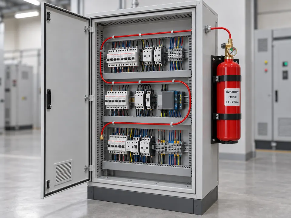
Illustrative application showing an FM200 suppression cylinder connected to an electrical panel
Illustrative view of an FM200 electrical panel protection application.

About the system

An FM200 automatic electrical panel suppression system with a 15 kg cylinder option; direct or indirect application is designed for the cabinet arrangement.

Explore panel components and how the system works
System provider
Özkartay
Capacity
15 kg
Extinguishing agent
FM200 (HFC-227ea)

System scope

  1. FM200 (HFC-227ea) extinguishing agent
  2. 15 kg cylinder capacity
  3. Direct or indirect cabinet protection is defined for the project
  4. Protected volume, detection and discharge arrangements are calculated together

Frequently asked questions

Which extinguishing agent does this panel system use?

This product family uses the FM200 (HFC-227ea) gaseous extinguishing agent.

How is cylinder capacity selected?

Assess cabinet volume, openings, ventilation and the selected system design limits together. A given cylinder capacity does not represent the same protected volume in every cabinet.

How are direct and indirect applications selected?

Select between a direct arrangement, where the detection tube also discharges the agent, and an indirect arrangement, where it triggers a valve feeding separate nozzles, using the cabinet layout and manufacturer design.

INSIDE THE PANEL SYSTEM

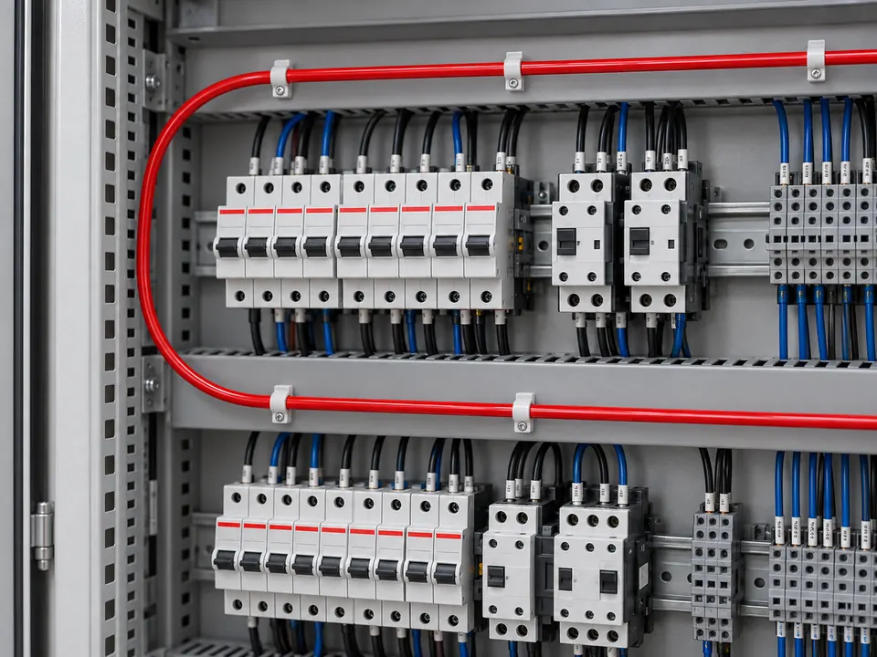
The red tube follows the detection route.

The cylinder, pneumatic valve and heat-sensitive tube work together. Explore the components and their arrangement inside a cabinet. The images represent a direct-discharge layout; the application depends on the selected system and project.

An open electrical cabinet with a sealed-end red detection tube routed along its equipment rows and a red suppression cylinder mounted upright outside.
Cylinder outside, detection tube inside — representative direct system.

Why does the tube follow the equipment rows?

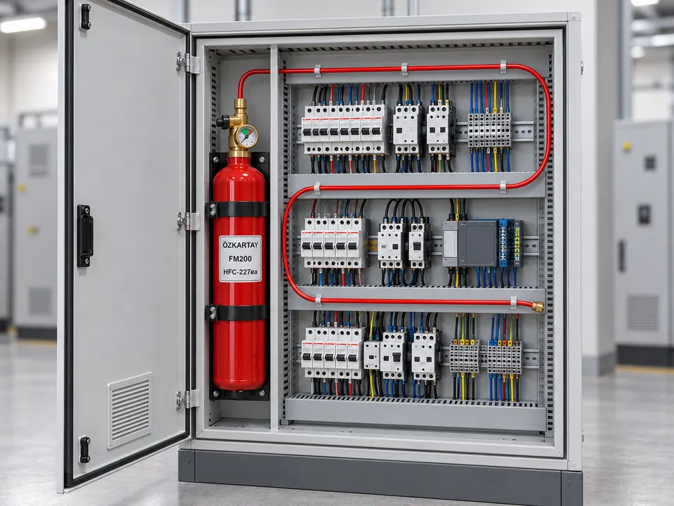
The detection tube is routed near the equipment being protected. Broad bends help avoid crushing the tube, while clips keep it in place. The cylinder can be mounted inside or outside the cabinet in an orientation permitted by the system.

See the cylinder mounted inside the cabinet
Representative cabinet application with a red cylinder mounted upright inside on the left and a red detection tube following the equipment rows.
Representative internal mounting. Position and orientation depend on the selected system’s requirements.

How does it work?

  1. Heat is detected

    The pressurised heat-sensitive tube ruptures at the fire’s hot spot.

  2. Pressure change triggers the valve

    A drop in tube pressure activates the pneumatic release arrangement.

  3. Agent is discharged

    The extinguishing agent follows the discharge path of the direct or indirect system.

Direct discharge

The same tube detects heat and carries agent to the rupture point. These illustrations do not include a separate discharge nozzle.

Indirect discharge

The detection tube triggers the valve; agent is distributed through a separate discharge line and nozzles. Components are selected for the particular system design.

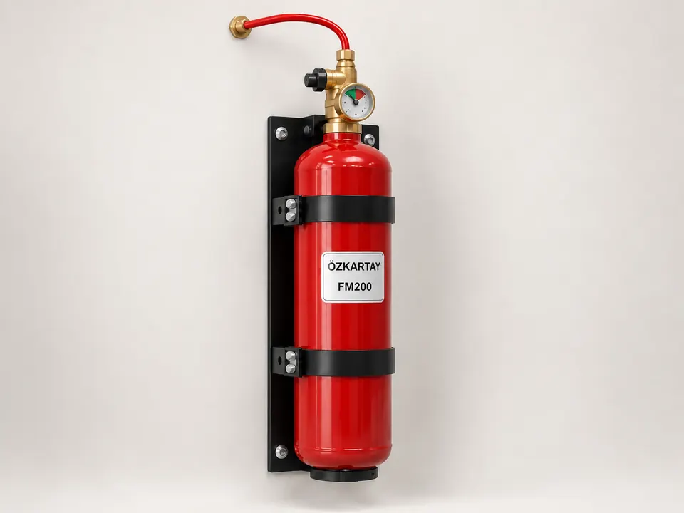
Representative red panel suppression cylinder mounted upright with two black straps and a backplate.

Representative component illustration

Cylinder and retaining bracket

The cylinder stores the extinguishing agent. Retaining straps and a backplate secure it to the selected mounting surface.

Why this shape or arrangement?
The cylindrical vessel provides pressurised storage; retaining straps limit movement of the cylinder.
What matters when selecting the component?
A model-permitted orientation, adequate support and access to the valve and gauge.
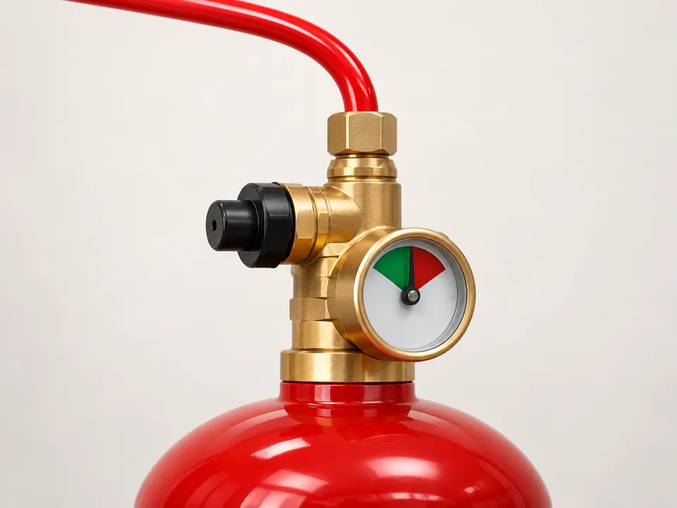
Representative close view of a pneumatic valve, small pressure gauge and red detection tube connection on a cylinder neck.

Representative component illustration

Pneumatic valve and gauge

The valve controls agent release from the cylinder. The gauge monitors the pressure circuit to which it is connected; the arrangement is model-dependent.

Why this shape or arrangement?
Connecting the detection tube to the valve lets a pressure change reach the release mechanism.
What matters when selecting the component?
Compatible connections, leak-tight seals and the correct gauge. Alarm or power isolation can require additional equipment.
Representative detail of a red detection tube clipped above electrical equipment with a broad return bend.

Representative component illustration

Heat-sensitive detection tube

This is a tube rather than an electrical wire. In a pneumatic system it is pressurised and ruptures at a point exposed to fire heat, triggering the system.

Why this shape or arrangement?
Its flexibility lets it follow different equipment rows. The route is selected around the identified risk points.
What matters when selecting the component?
Uncrushed bends, secure clips and protection at sharp-edged openings.
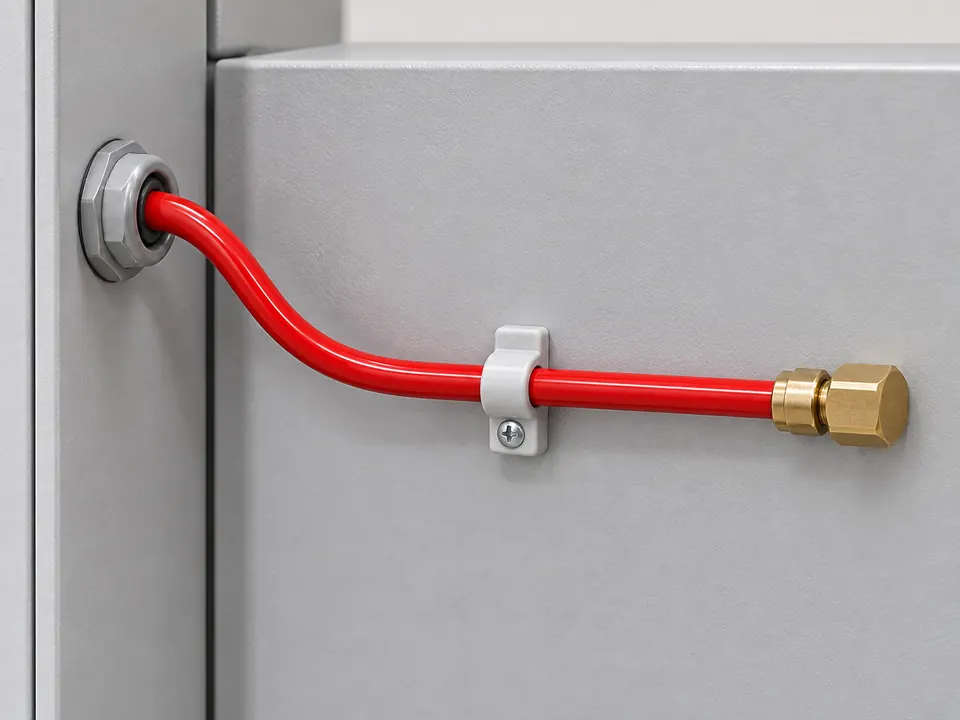
Representative detail of a closed brass tube termination, retaining clip and protected cabinet opening.

Representative component illustration

Fittings, clips and end-of-line closure

Fittings connect the tube to the valve and its termination. A closed end-of-line fitting allows the detection circuit to remain pressurised.

Why this shape or arrangement?
Clips retain the route; a protected opening reduces rubbing against a metal edge. The end of the detection circuit is closed.
What matters when selecting the component?
System-compatible fittings and tubing, leak-tight joints and access for servicing.

Design and installation guide

15 kg FM200 (HFC-227ea) automatic electrical panel suppression system: selection and application guide

This 15 kg FM200 (HFC-227ea) option is assessed for local suppression inside an electrical cabinet or suitable enclosed equipment. Cylinder capacity alone does not define the protected cabinet volume; agent quantity, openings and the chosen discharge arrangement are assessed together.

Offered for local fire protection in electrical, automation, server and UPS cabinets. Select cylinder capacity from enclosure volume, equipment layout, openings and ventilation. Arrange detection tubing, pipework and any discharge nozzles according to the selected system design.

01

Selection, placement and maintenance

Selection considers the product function, the protected risk and operating conditions together. These steps support the site survey and quotation.

  1. Cabinet and hazard data

    Record cabinet dimensions, equipment layout, cable penetrations and fire load during the survey. A shared cylinder for separate cabinets is assessed only within a design supported by the selected system.

  2. Agent quantity and openings

    Determine FM200 quantity from the protected volume and required design conditions. Assess fans, vents and door openings for agent loss during discharge.

  3. Detection and discharge arrangement

    Select a direct or indirect arrangement through compatibility of the detection tube, valve and any separate nozzle line. Route detection around hazard points and include alarm and power coordination in the project.

  4. Commissioning and operating records

    Check installation, connections and the release scenario against manufacturer instructions. Include cylinder charge, detection tubing and alarm connections in maintenance, with service verification before restoring a discharged system.

02

Applications and site planning

These examples show why placement and equipment requirements can differ between facilities using the same product.

Production-line electrical cabinets

Site requirement
Cable density, fans and covers opened during maintenance.
Application approach
Define protection by cabinet and include cover and fan states in the suppression scenario.

Control and automation enclosures

Site requirement
Sensitivity to downtime and separate internal compartments.
Application approach
Plan detection and discharge around the compartments. Assess the relationship between cabinet protection and room-level detection and suppression separately.

03

Pre-quotation checklist

Scroll the table horizontally to view every column.

Pre-quotation checklist
Check itemProduct / applicationInformation to assess
Cylinder option15 kgRequired agent quantity and protected volume
AgentFM200 (HFC-227ea)Selected system technical documentation
VentilationFans, vents and cable penetrationsOpenings and power scenario during discharge
HandoverInstallation, function checks and maintenance recordsDetection, alarm and restoration plan

Select cabinet capacity through a design informed by enclosure volume and operating conditions. Cabinet dimensions, photographs and ventilation data allow us to determine the FM200 option and installation scope together.