
Design and installation guide
CO₂ (carbon dioxide) suppression systems: selection and application guide
CO₂ suppression may be designed for local application or enclosed-volume protection in suitable industrial processes. Extinguishing concentrations pose a serious hazard to people; access control, evacuation and safe operation are central to selection.
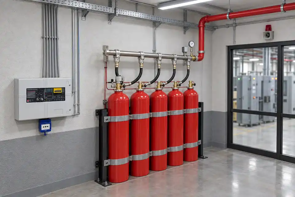
A CO₂ suppression system controls fire by reducing oxygen concentration and creating a cooling effect as the gas expands. It is designed for unoccupied areas or spaces that can be safely evacuated during discharge, such as transformer and power rooms, cable galleries, motor/generator rooms, paint booths, electrical control rooms, computer rooms and areas with sensitive equipment.
01
Engineering and commissioning steps
Selection considers the product function, the protected risk and operating conditions together. These steps support the site survey and quotation.
Defining the protected space
Establish local application or total-flooding needs with the process hazard and personnel access. Assess migration and potential accumulation in adjacent areas.
Agent, piping and nozzle calculations
Determine cylinders, agent quantity, pipe route and nozzle distribution using the selected system calculation method. Pressure or discharge data from one system is not transferred to another agent or model.
Detection, evacuation and interlocks
Design pre-discharge warning, evacuation, restricted access, manual controls and safe maintenance isolation together. CO₂ discharge is not planned as an operating scenario with people remaining in the protected area.
Integrity and handover checks
Verify required function tests, piping checks and process interlocks during commissioning. Re-entry follows authorised confirmation that the atmosphere is safe, with operating and maintenance records handed over.
02
Applications and site planning
These examples show why placement and equipment requirements can differ between facilities using the same product.
Unoccupied industrial processes
- Site requirement
- Local fire hazard and access to process equipment.
- Application approach
- Assess nozzle placement and access safeguards with process shutdown.
Suitable enclosed machinery spaces
- Site requirement
- Volumes where gas may accumulate and migrate to adjacent areas.
- Application approach
- Define total-flooding protection, evacuation and safe re-entry in the same engineering assessment.
03
Pre-quotation checklist
Scroll the table horizontally to view every column.
| Check item | Product / application | Information to assess |
|---|---|---|
| Agent | CO₂ | Hazard, system model and technical documentation |
| Protection boundary | Local application or total flooding; design-dependent | Volume, openings and adjacent spaces |
| Personnel safety | No personnel in the CO₂ discharge area | Access, manual controls and operating plan |
| Commissioning | Calculations, installation and function tests | Process interlocks and safe re-entry |
Gaseous protection requires more than naming an agent and selecting cylinders. We can define the facility scope through a coordinated survey, flow calculation, detection scenario and operating-safety assessment.