
Design and installation guide
Low- and medium-expansion foam systems for industrial flammable-liquid protection
Production facilities, petrochemical sites and storage areas handle Class B liquids such as petrol, diesel, crude oil, solvents and alcohol, each presenting different fire hazards. The suppression method is selected for the chemical properties of the liquid. Many hydrocarbons are lighter than water, and unsuitable water-jet application can spread the fuel. Water-miscible polar solvents require separate assessment of foam and fuel compatibility.
Low- and medium-expansion systems introduce air into a solution of water and suitable foam concentrate. The blanket formed on the liquid surface helps limit vapour release and control the fire. Concentrate family, expansion class, application flow and discharge equipment are matched within the same design.
01
Expansion ratio and suppression mechanism
Expansion ratio is the volume of finished foam divided by the original foam-solution volume. For example, 20 litres of foam produced from 1 litre of solution represents an expansion ratio of 20:1.
Low expansion: up to 20:1
Approximately 1:1–20:1 produces a denser, more fluid blanket. Low-expansion equipment can deliver foam to a tank surface or more distant application points at suitable flow and pressure. Wind, nozzle selection and layout are assessed together in the design.
Medium expansion: the 20:1–200:1 range
A lighter, more voluminous structure is used to cover spill surfaces with a substantial foam layer. Application is generally local or close to the surface. Actual expansion depends on concentrate, generator, air intake and operating conditions.
Blanketing and smothering
A continuous blanket limits contact between the fuel surface and air. Application is planned to maintain blanket continuity and avoid unnecessary disturbance of the fuel.
Cooling
Water contained in the foam absorbs heat from the fuel and surrounding hot surfaces. Cooling performance is assessed using the applied solution quantity, surface temperature and contact conditions.
Vapour suppression and reignition control
A stable layer helps reduce the release of flammable vapours from the surface. Blanket disruption, hot surfaces and fuel movement are included in assessment of reignition risk.
02
System components and engineering details
Concentrate selection, proportioning and hydraulic calculations are coordinated with the documented operating range of the foam chamber, monitor, sprinkler or generator.
Foam concentrates and fuel compatibility
- AFFF
- AFFF is a fluorinated foam family capable of forming an aqueous film on suitable hydrocarbon fuels. The product and application scope are matched to its data sheet.
- AFFF-AR and alcohol-resistant products
- Alcohol-resistant products compatible with the fuel are selected for polar-solvent hazards such as alcohols, esters and ketones. Barrier formation and application method are assessed against the documented fuel scope of the concentrate.
- NFF / F3 / SFFF
- Suitable non-fluorinated options are assessed for new systems and conversions. Manufacturer statements of no intentionally added PFAS are considered alongside fuel compatibility, the SDS and hardware tests. Polar solvents require a suitable alcohol-resistant NFF product.
Discharge and application equipment
- Low-expansion equipment
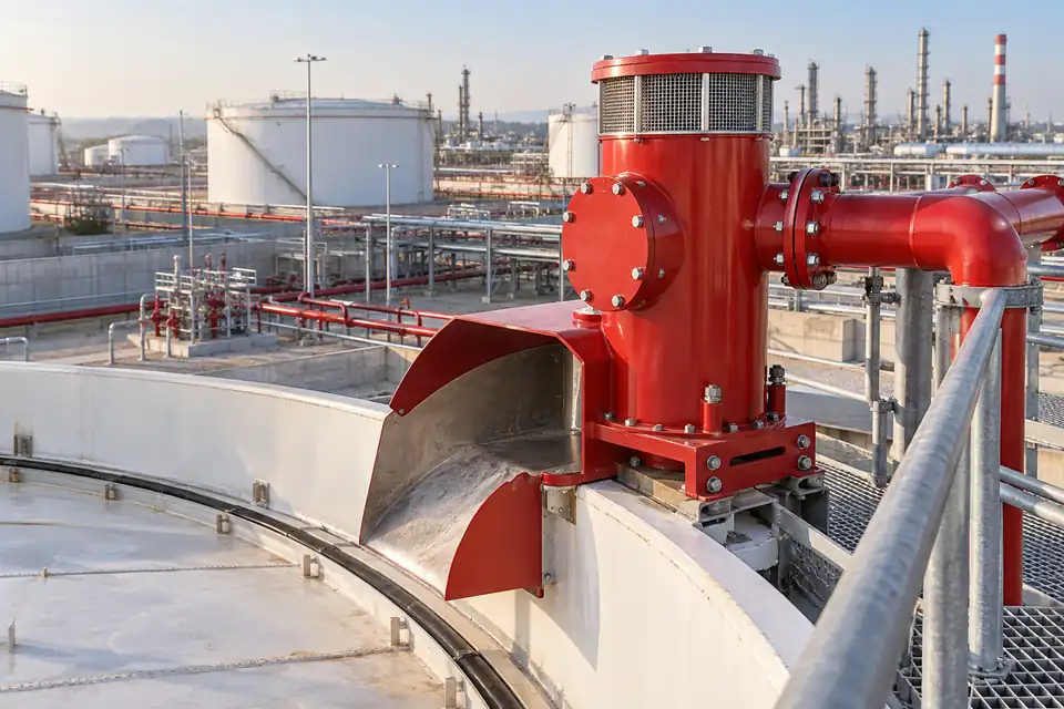
- Foam chambers, floating-roof rimseal nozzles, suitable foam sprinklers and fixed or remotely controlled monitors are used for surface protection. Equipment is assessed as a documented combination with the selected concentrate.
- Medium-expansion equipment
- Medium-expansion generators, suitable pourers and hand-held branchpipes apply foam to spill or containment areas. Discharge height, air intake and the route to the fuel surface are established in the design.
Supply, proportioning and control
- Water and concentrate supply
- The water source, concentrate tank and proportioner are selected for design flow. Concentration, discharge duration and the required concentrate quantity are calculated for the product and project requirements.
- Hydraulic calculation and layout
- Pipe diameters, pressure losses, application area and discharge-device demand are calculated together. Monitor reach or foam depth is verified using selected equipment data.
- Detection, testing and management after use
- Automatic detection or control sequences, maintenance access and functional tests are planned. Collection of used foam and contaminated firefighting water is included in facility environmental management.
03
Applications and facility-specific arrangements
Expansion class is selected together with liquid type and storage geometry. Wind in open areas and ventilation indoors influence the application method.
Fuel storage tanks
- Hazard and site requirement
- Large fuel surfaces in vertical tanks and the seal area around floating roofs.
- Application approach
- Low-expansion foam chambers or rimseal arrangements are assessed. Controlled delivery to the fuel surface is designed for tank geometry and wind conditions.
Tank spill and bund areas
- Hazard and site requirement
- Fuel accumulation around tanks, the spill surface and vapour release.
- Application approach
- Surface coverage is planned using a suitable medium-expansion generator or pourer. Area, drainage, application flow and required foam depth are determined together.
Loading gantries and tanker stations
- Hazard and site requirement
- Vehicle movement, open or partly enclosed areas and spill risk during fuel transfer.
- Application approach
- Foam-water sprinkler piping, suitable nozzles or monitors are selected for the hazard layout. Reach and wind effects on low-expansion application are considered in the calculations.
Shipyards, jetties and marine facilities
- Hazard and site requirement
- Loading lines, fuel-transfer points, exposed wind conditions and available water supplies.
- Application approach
- A suitable low-expansion monitor arrangement is assessed. Reach, flow, remote control and fresh/seawater compatibility are verified for the selected hardware and concentrate.
Chemical storage and process areas
- Hazard and site requirement
- Polar solvents, spill channels, containment areas and formation of flammable vapours.
- Application approach
- Fuel-compatible concentrate, including alcohol-resistant NFF where needed, is matched to suitable expansion equipment. Foam coverage is planned together with ventilation and other hazard controls.
04
Comparison of low- and medium-expansion systems
Scroll the table horizontally to view every column.
| Technical parameter | Low expansion | Medium expansion |
|---|---|---|
| Expansion ratio | Up to 20:1; approximately the 1:1–20:1 range. | Approximately the 20:1–200:1 range. |
| Foam structure | Denser and more fluid, with higher water content. | Lighter, bulkier and sponge-like. |
| Wind and outdoor conditions | Assessed for outdoor application; wind effects are considered. | More sensitive to air currents because of its lighter structure. |
| Reach and application distance | Depends on monitor/nozzle selection, flow and pressure. | Generally local discharge or application close to the surface. |
| Suppression approach | Surface blanketing, cooling and vapour suppression. | Deep surface blanketing and voluminous spill coverage. |
| Typical equipment | Foam chamber, rimseal nozzle, monitor and suitable sprinkler. | Medium-expansion generator, suitable pourer and branchpipe. |
| Application area | Fuel tanks, jetties and loading gantries. | Tank bunds and suitable chemical spill areas. |
Expansion values describe classes rather than product performance, fixed reach or application flow. Actual operating values for concentrate and hardware are established using the selected system documentation.
Share the flammable-liquid inventory, storage layout and site conditions so we can assess the appropriate expansion class, concentrate and application equipment together.