
Skip to content

Fire safety design and engineering.

System design aligned with technical specifications and site conditions, supported by hydraulic calculations and installation drawings ready for the field.

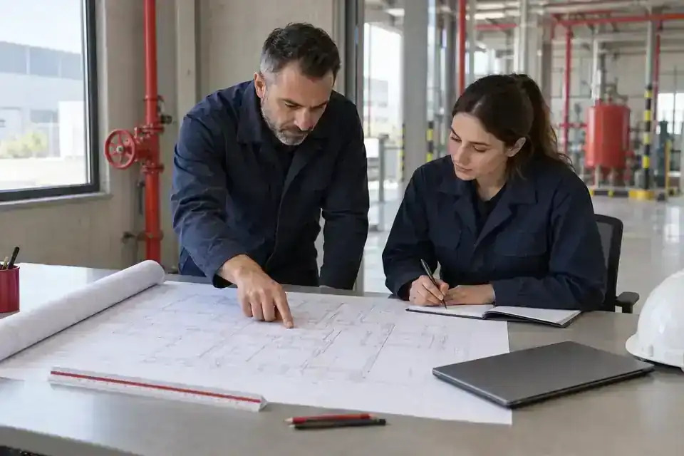
Engineers reviewing installation drawings for a fire protection project together
Engineering calculations and installation drawings bring the design to the field.

Field and engineering

From theory to seamless implementation.

Addressing the hazards identified by a fire risk assessment requires a sound design and engineering process. Engineering is the critical stage where abstract risk data becomes protective and preventive mechanical and electronic systems. Successful design maximises the protection of people and property, while incorrect or incomplete calculations can have irreversible consequences in an emergency.

01

How is the design process carried out, and what must it consider?

Design and engineering activities follow scientific and technical data specific to the facility, rather than arbitrary or general rules. The process has four building blocks:

  1. Alignment with site conditions and specifications

    The systems must fully align with the project’s technical specifications and existing site conditions. Building architecture, ceiling height, airflow and structural elements are considered when designing the most suitable system for the facility.

  2. Water, foam and gas flow calculations

    Hydraulic calculations are performed for water and foam systems, with agent-specific flow calculations for gaseous systems. Appropriate engineering software checks pressure and flow at the critical nozzle or sprinkler head. Water and foam calculations assess pump capacity, pipe diameters, water storage and foam concentrate requirements; gas calculations assess agent quantity, cylinder arrangement, piping and discharge time.

  3. Preparation of installation drawings

    Once the calculations and design are complete, field-ready shop drawings allow installation teams to build the system accurately. The drawings include pipe routes, equipment positions, hanger and support details, and isometric diagrams.

  4. Coordination across disciplines (BIM/3D modelling)

    Three-dimensional coordination software is used for clash detection so that fire-protection pipework does not conflict with ventilation, electrical services, plumbing or architectural elements.

02

Engineering and design solutions for different facilities

Each facility has a different architecture and hazard classification, so its engineering solution must be tailored accordingly:

Production facilities

Engineering approach
Dedicated pipe routes are defined for machinery that generates high heat and for large, open factory areas.
Design solution
Hydraulic calculations consider the hazard classification at the most remote point of the facility, such as Extra Hazard. Seismic protection, including seismic hangers and flexible joints, is integrated into the pipework design.

Logistics and high-bay warehouses

Engineering approach
Rack layout, the combustibility of stored materials and packaging type form the basis of the design.
Design solution
The system is designed to match the roof slope and rack layout. Hydraulic calculations precisely determine the water demand of high-flow ESFR sprinklers or in-rack pipework systems.

Data centres and archive buildings

Engineering approach
Clean-agent suppression systems are the focus in spaces where water could cause damage.
Design solution
Gas-discharge flow and hydraulic calculations take room integrity and Door Fan Test requirements into account so the intended concentration is reached within the specified time, for example within 10 seconds. Field-ready isometric drawings are detailed around the arrangement of electrical panels and server cabinets.

Hotels, hospitals and shopping centres (complex buildings)

Engineering approach
In buildings with high occupancy, evacuation scenarios and mechanical systems are designed to work together.
Design solution
Pressurisation and smoke-extraction fan capacities are calculated aerodynamically to limit smoke spread during a fire. The system design follows the building’s complex architecture and site conditions while considering appearance, including concealed sprinklers where appropriate.

Risk assessment identifies what needs to be protected; professional design and engineering determine how it will be protected and which calculations support the solution. A reliable fire-protection system depends on correct hydraulic calculations and complete installation drawings that can be put into practice on site.

Let’s plan your facility’s fire-protection design together.

Request design and engineering