
Design and installation guide
Foam-water sprinkler systems for flammable-liquid hazards
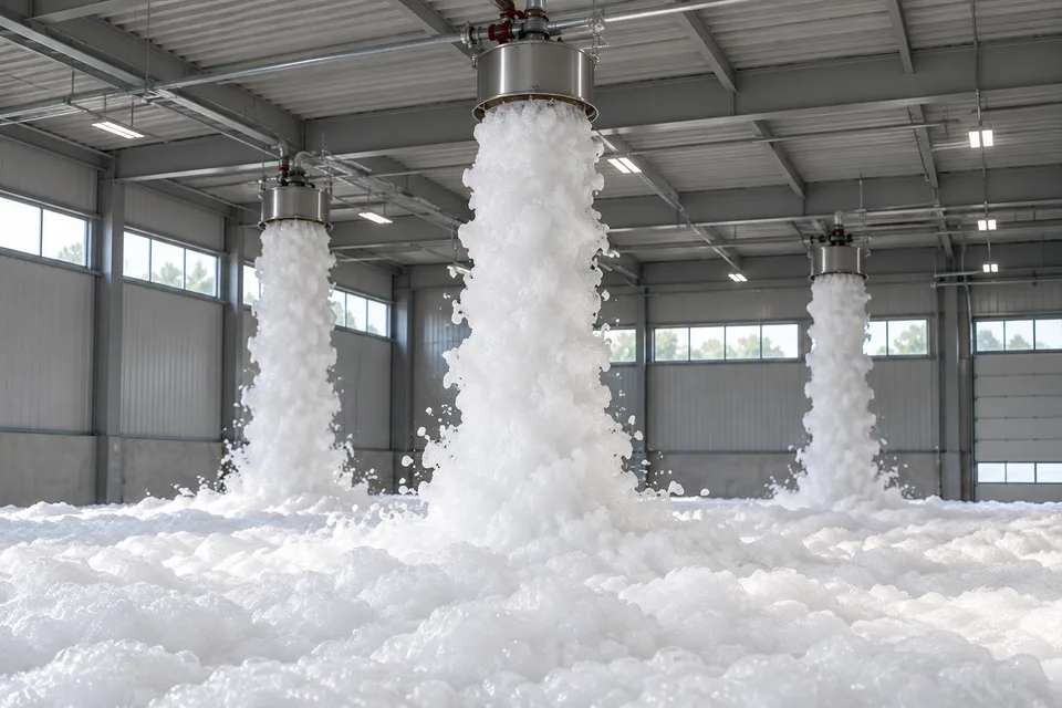
A foam-water sprinkler system proportions suitable concentrate into water and applies the solution through sprinklers or spray nozzles. The resulting foam blanket helps limit vapour release, control the fire and cool the hazard. Selection takes account of the liquid’s interaction with water and the application conditions.
Design considers the foam-water scope of current NFPA 11 and applicable provisions such as NFPA 30 for liquid hazards or NFPA 409 for hangars. The former NFPA 16 scope has been incorporated into NFPA 11. Application density, discharge duration, proportioner and sprinkler compatibility are established within the same project design.
01
Foam solution and suppression mechanism
Foam concentrate, water and the discharge device are selected as a system compatible with the fuel.
Water-concentrate proportioning
The proportioner adds a controlled amount of concentrate to water throughout the design flow range. Ratios such as 1%, 3% or 6% are used only according to the selected concentrate, fuel and equipment documentation; proportions are not transferred between different products.
Surface blanket and vapour suppression
A stable blanket reduces fuel-surface contact with air and the release of flammable vapours. Aqueous-film formation or barrier formation on polar solvents depends on the concentrate family; not all products, including NFF, use the same film mechanism.
Cooling and continued water supply
Water within the solution absorbs heat from surfaces. Continued water cooling after foam application is determined from potential fuel spread, drainage and the design scenario. Foam and water durations are not assumed identical for every facility.
Hydraulic density and coverage
Required solution flow is calculated from the application density in L/min/m² and the operating area. Proportioner inlet pressure, pipe losses, discharge-device flows and simultaneous demand are verified together.
02
Concentrate, equipment and commissioning
Correct proportioning, fuel compatibility and sprinkler combinations are verified under documented operating conditions.
Concentrate and supply assembly
- AFFF, AFFF-AR and NFF options
- The portfolio is not limited to AFFF and AFFF-AR; suitable NFF/F3/SFFF products are also considered. Alcohol resistance and fuel scope are verified for polar solvents. Changing concentrate requires coordinated checks of the tank, proportioner, viscosity, water type and sprinkler combination.
- Bladder tank
- The bladder separates concentrate from water, and water pressure supplies concentrate to the proportioner. Operating flow and pressure ranges and usable tank capacity depend on the selected system. A bladder tank does not imply that all detection and control functions are power-independent.
- Balanced pressure and ratio controller
- Suitable foam pumps and balanced-pressure proportioning may be considered for multi-zone applications or wide flow ranges. Venturi or other proportioning arrangements are matched to water-concentrate pressure relationships and the manufacturer’s operating range.
Valves and discharge arrangements
- Deluge
- Open nozzles or sprinklers receive solution through the main valve opened by the detection and release sequence. Discharge devices in the designed zone operate together; manual release and alarm interfaces are arranged within the project.
- Wet-pipe and pre-action
- In a wet-pipe arrangement, closed sprinklers open on heat. In a pre-action arrangement, the relationship between detection, admission of water or solution and sprinkler operation depends on the selected interlock arrangement. Not every pre-action system uses the same double-confirmation sequence.
- Air-aspirating devices
- Air inlets introduce air into the solution. Expansion class, finished foam and discharge pattern depend on the selected device; an aspirating sprinkler is not automatically a HI-EX high-expansion generator.
- Non-aspirating devices
- Suitable non-aspirating devices may be used with AFFF/AFFF-AR or documented NFF combinations. The approved device-concentrate-fuel scope is checked together with pressure and application density.
Testing and maintenance
- Commissioning and functional tests
- Detection, manual release, valve operation, alarms and pump sequences are verified by controlled tests. Usable tank capacity, line cleanliness, drainage and collection arrangements are recorded at handover.
- Concentrate analysis
- Concentrate is sampled using the manufacturer’s method, and the required pH, viscosity, sediment and other performance checks are assessed. Sampling and testing intervals follow the adopted maintenance standard and product instructions.
- Proportioning measurement
- A suitable refractometer or conductivity method is used with a calibration curve for the selected concentrate. The measured ratio is compared with its approved acceptance limits. Test discharge and flushing water are included in the environmental collection and management plan.
03
Applications and fuel selection
The solution is developed for the actual arrangement of the Class B liquid hazard and the equipment’s documented fuel scope.
Aircraft and helicopter hangars
- Hazard and site conditions
- Fuel spills, wide spans and limited access beneath wings.
- Application approach
- Expanded foam and a specialised concentrate selected for the combustible material are assessed. Overhead or local discharge, under-wing coverage and detection sequences follow the hangar design basis.
Paint, solvent and chemical storage
- Hazard and site conditions
- Different liquids and polar solvents in drums, IBCs or racks.
- Application approach
- Concentrate options including alcohol-resistant NFF compatible with the fuel are assessed together with rack or overhead sprinklers and the storage arrangement.
Fuel loading and filling areas
- Hazard and site conditions
- Spill and ignition risks at open or partly enclosed loading bays.
- Application approach
- Suitable detection and zoned foam-water spray are designed with wind, surface drainage and vehicle positions.
Transformer and turbine areas
- Hazard and site conditions
- Hot oil surfaces, equipment geometry and electrical safety.
- Application approach
- Suitable oil and equipment protection is assessed through cooling and coverage calculations. Water or foam use is coordinated with electrical isolation and the applicable protection basis.
04
Compare foam-water system arrangements
Scroll the table horizontally to view every column.
| Arrangement | Sprinkler / nozzle | Operating sequence | Selection focus |
|---|---|---|---|
| Deluge | Open discharge devices. | Detection or manual release supplies the zone. | Rapid spread and simultaneous area coverage. |
| Wet pipe | Closed heat-operated sprinklers. | Sprinklers exposed to heat operate. | Fuel, storage and sprinkler-concentrate compatibility. |
| Pre-action | Closed sprinklers and control valve. | The selected single/double interlock arrangement. | Detection, pipe conditions and unwanted-release control. |
Share fuels, storage layout and the existing water supply with Özkartay so concentrate, proportioning and sprinkler options can be assessed as a compatible system.