
Design and installation guide
Protection for large volumes: HI-EX high-expansion foam suppression systems
Direct access to a fire can be difficult in high-bay warehouses, hangars, tunnels and spaces with complex equipment layouts. HI-EX applies large volumes of foam to cover surfaces and the defined protection volume.
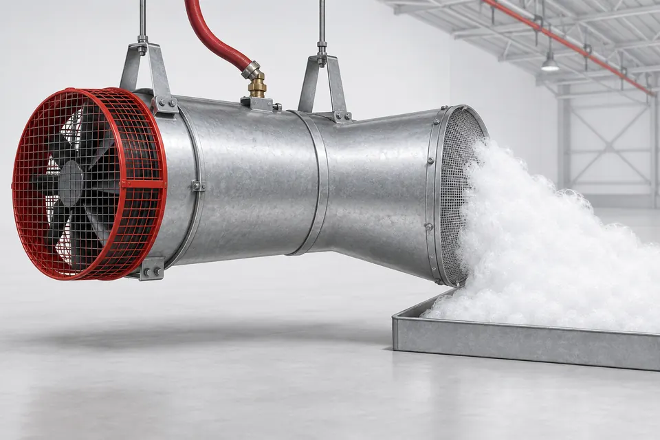
Introducing air into foam solution creates a lightweight, high-expansion structure. Typical HI-EX equipment expansion is approximately 200:1–1000:1, depending on concentrate, generator and operating pressure. For total flooding, the required fill height and filling time are calculated for the hazard and enclosure geometry.
01
How does HI-EX work?
Expansion ratio relates finished-foam volume to original solution volume. For example, 600 litres of foam from 1 litre of solution represents 600:1 expansion. Suppression is supported by blanketing, cooling and limitation of heat transfer.
Volume blanketing and smothering
Foam from the generator spreads through the protected area and limits contact between burning material and air. The aim is to cover the defined hazard to the required foam height.
Evaporation and heat absorption
Water within the foam absorbs heat at hot surfaces and can evaporate. Heat absorption and the resulting water vapour contribute to suppression, with performance assessed for actual fire and application conditions.
Cooling material surfaces
Cooling at surfaces contacted by foam solution helps control the fire and reduce reignition risk. Material type and foam access to these surfaces are considered in the design.
Limiting heat spread
Accumulated foam forms a layer between burning material and surrounding equipment and materials. Blanket stability, heat exposure and enclosure layout are assessed together.
02
Components, design and system benefits
HI-EX design coordinates generator air demand and foam production with water/concentrate supply, enclosure openings and the operating sequence.
Foam production and mechanical components
- Concentrate for high expansion
- A concentrate producing stable foam is selected for compatibility with the generator and combustible material. Expansion, drainage and fuel scope are checked using the product data.
- Water-driven generators
- In this type, pressurised water drives a turbine and fan. Air passes through a foam screen supplied with solution to produce foam. Operation requires adequate water flow and pressure.
- Electric or pneumatic drive options
- Fan drives vary with generator model. The power source, operational continuity and required airflow are designed using the selected equipment instructions.
- Proportioner and supply piping
- The proportioner adds concentrate to water at the documented use concentration. Tank volume, concentration and piping capacity are determined for total generator demand and required operating duration.
Volume and operating calculations
- Fill height and filling time
- Net protection volume, equipment obstructions, foam losses and the required fill level are calculated. Generator quantity and layout are sized using these results.
- Air intake and enclosure openings
- Generator use of inside or outside air is assessed for smoke and temperature conditions. Doors, ventilation and foam loss through openings form part of the design.
- Detection, warning and evacuation
- Activation, required warnings and occupancy conditions are planned together. The effects of voluminous foam on visibility and escape are addressed in the operating plan.
Application-dependent benefits
- High foam volume
- High expansion produces large foam volumes from a unit volume of solution. Water and concentrate demand are compared using engineering calculations for the same hazard and performance target.
- Lower liquid content
- High-expansion foam contains less liquid per unit volume. This can help reduce wetting effects in suitable applications; cleaning and material compatibility are still planned.
- Access within complex layouts
- Foam can spread around equipment and into open spaces that are difficult to reach with direct discharge. Rack layouts, closed packaging and obstacles limiting foam movement are included in project assessment.
03
HI-EX applications
HI-EX is especially considered for spaces where airflow and foam retention can be managed. Fuel type, protection height, occupancy and integration with other protection systems are assessed together.
Aircraft and helicopter hangars
- Site requirement
- Large floor areas, high ceilings, fuel hazards and access obstacles around aircraft.
- HI-EX design approach
- Expanded foam is combined with a specialist concentrate selected for the combustible material. Generator layout, floor geometry, required coverage and evacuation arrangements are designed together.
High-rack warehouses and logistics centres
- Site requirement
- Vertical spread between racks, narrow aisles and complex storage arrangements.
- HI-EX design approach
- Foam movement into open spaces and achievement of the required fill level are assessed. Commodities, packaging, rack obstructions and existing sprinkler protection are considered together.
Cable tunnels, underground facilities and mines
- Site requirement
- Long or restricted-access routes, cable loads and air currents.
- HI-EX design approach
- Generator position, foam travel, compartmentation and losses through openings are calculated. Suitability is assessed for the combustible material and evacuation arrangements.
Ship engine rooms and cargo holds
- Site requirement
- Confined machinery layouts, fuel leaks and marine operating conditions.
- HI-EX design approach
- Generator, concentrate and water supply are matched to the documented marine application. Protection volume around machinery and air supply are defined in the design.
Chemical and solvent storage
- Site requirement
- Flammable spills, fuel compatibility and vapour formation.
- HI-EX design approach
- Concentrate compatibility with the chemical is verified. Blanketing and volume application are coordinated with ventilation and other hazard controls.
04
Foam systems by expansion class
Scroll the table horizontally to view every column.
| Property | Low expansion | Medium expansion | HI-EX high expansion |
|---|---|---|---|
| Expansion ratio | Up to 20:1. | Approximately 20:1–200:1. | Typically approximately 200:1–1000:1; equipment-dependent. |
| Protection approach | Blanketing the flammable-liquid surface. | Blanketing spill and containment surfaces. | Covering the defined hazard volume to the required height. |
| Foam structure | Dense and fluid. | Lightweight and voluminous. | Very lightweight, with high air content. |
| Water and concentrate calculation | Based on surface area, flow and duration. | Based on surface coverage, expansion and duration. | Based on volume, fill level, time and foam losses. |
| Air and wind effects | Outdoor conditions and delivery are assessed together. | More sensitive to air currents. | Air supply, openings and foam retention are critical. |
| Typical applications | Tanks, jetties and loading gantries. | Tank bunds and suitable spill areas. | Suitable hangars, warehouses, tunnels and holds. |
Expansion ratios and application examples do not define a common filling time or water-saving guarantee for all facilities. Actual performance is established for the selected concentrate–generator combination and project calculations.
Share the protected volume, combustible material and operating conditions so we can assess HI-EX generator layout, supply requirements and the protection sequence together.