
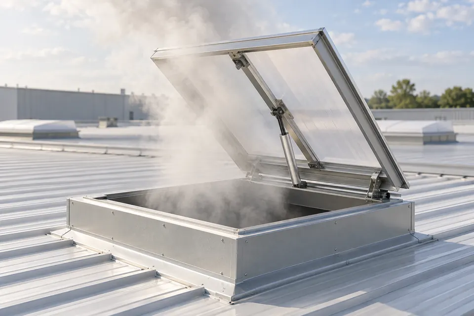
Design and installation guide
Natural smoke and heat exhaust systems: airflow balance, controls and maintenance
Natural smoke and heat exhaust ventilation systems (NSHEVS) use the buoyancy of hot gases to direct smoke through roof or high-level facade openings. Designed with low-level air inlets, the system aims to support evacuation and fire-service access and reduce the effects of hot smoke on the structure.
Design is assessed against the Turkish Regulation on Fire Protection of Buildings and the project basis. The performance scope of natural smoke and heat exhaust ventilators is checked against EN 12101-2, and required smoke barriers against EN 12101-1. The ventilator, actuator and control arrangement are assessed together with the selected device’s documented performance.
01
Smoke layers and balanced airflow
Vent openings, smoke reservoirs and low-level air supply are calculated together to establish the natural flow arrangement.
Hot gases rise
Fire-heated gases become less dense and rise to form a smoke layer beneath the ceiling. Building height, fire size and temperature difference are inputs to the exhaust calculation.
Smoke reservoirs and barriers
Roof geometry or suitable smoke barriers form the designed reservoirs. Barrier positions, openings and performance are selected to manage horizontal smoke spread.
Natural high-level exhaust
When a roof ventilator or high-level facade opening operates, buoyancy and pressure differences drive smoke outside. Aerodynamic free exhaust area, wind effects and device location are included in the calculation.
Low-level replacement air
Doors, windows or automatic inlets supply air to replace exhausted gases. Inlet area and air velocity are balanced with exhaust to avoid disrupting the smoke layer. Conditions for the intended clearer lower layer are verified for the design fire.
02
Opening arrangements, calculations and operation
The control type is selected with device load and temperature classes; comfort ventilation is coordinated with the fire sequence.
Control and activation options
- Pneumatic opening
- In suitable systems, a sealed CO₂ cylinder or documented gas supply operates pneumatic cylinders. The core opening function can be arranged independently of electricity; operation under snow and wind loads depends on the device’s tested class. Gas lines and opening geometry follow the manufacturer arrangement.
- Electric actuators
- Chain, linear or arm actuators are selected for compatibility with the ventilator and control panel. Low-voltage arrangements such as 24 V DC and other supply options may be available. Comfort ventilation and rain or wind sensors are managed according to fire-mode priority.
- Local thermal activation
- A fusible element or glass bulb provides local activation only in a documented device arrangement incorporating that function. Activation temperature and the means of operating independently of controls depend on the selected equipment; not every ventilator has the same thermal element.
- Manual controls and alarm integration
- The fire-detection panel and accessible manual smoke-ventilation controls initiate the defined zone sequence. Operation of smoke barriers, high-level openings and air inlets is coordinated in the project, with control and fault status monitored.
Device and airflow-area calculations
- Aerodynamic free exhaust area
- Geometric ventilator dimensions and effective exhaust area are different. Required aerodynamic free exhaust area is calculated from device performance, design fire, smoke reservoir and target layer height; low-level inlet area is checked separately.
- Snow, wind and temperature classes
- Device snow-load, wind-load, temperature, opening-reliability and use classes are matched to site conditions. Actuator type alone does not establish load resistance. Opening angle and surrounding obstructions are assessed against the device’s documented geometry.
- Power continuity and system coordination
- In electrical arrangements, battery capacity, standby duration and required opening or closing cycles are established together. A 72-hour backup rating on a particular panel refers to standby duration, not 72 hours of continuous motor operation. Sprinklers, ventilation and escape arrangements are coordinated with the smoke-exhaust design.
Commissioning, testing and maintenance
- Zone and functional tests
- Manual controls, fire alarms, ventilator opening, air inlets and relevant barrier functions are verified through controlled tests. Transition from comfort ventilation to fire mode and fault-monitoring sequences are recorded.
- Equipment-specific maintenance
- Pneumatic arrangements require checks of small gas cylinders or gas supply, lines and opening cylinders; electrical arrangements require battery, supply and actuator checks. Hinges, seals, fixings and surrounding clearance are inspected in both. Testing and replacement intervals follow manufacturer programmes and the applicable maintenance basis.
- Building changes
- Changes to rack height, partitions, roof equipment, air inlets or occupancy may affect smoke reservoirs and flow conditions. Changes are reassessed against the existing calculation and zone sequence.
03
Natural exhaust by building type
Roof geometry, smoke reservoirs, air inlets and occupancy require different choices for each building.
Logistics centres and warehouses
- Building conditions
- Large roofs, high racks and varying fire loads.
- Application approach
- Roof ventilators or rooflight integration are assessed with smoke reservoirs, rack layout and documented load classes.
Production facilities
- Building conditions
- Process heat, normal ventilation needs and smoke generation during fire.
- Application approach
- Comfort ventilation and fire exhaust are combined through compatible devices and a control sequence giving priority to fire operation.
Shopping centres and atria
- Building conditions
- Glazed roofs, tall spaces and high visitor occupancy.
- Application approach
- Facade or roof openings, suitable actuators and any required smoke barriers are selected with the architectural layout and exhaust calculation.
Sports, exhibition and event venues
- Building conditions
- Wide spans and variable occupancy.
- Application approach
- High-level exhaust and low-level air inlets are coordinated within the same zone sequence, taking escape routes and temporary layouts into account.
04
Compare pneumatic and electric control arrangements
Scroll the table horizontally to view every column.
| Feature | Pneumatic arrangement | Electric arrangement |
|---|---|---|
| Opening power | A suitable sealed gas cylinder or documented gas supply. | A compatible supply and required battery backup. |
| Operation under load | Depends on the selected device’s tested class. | Depends on the selected device’s tested class. |
| Comfort ventilation | With a suitable dual-purpose arrangement and controls. | With a suitable actuator and fire-priority controls. |
| Local thermal activation | Where incorporated in documented equipment. | Where incorporated in documented equipment. |
| Maintenance focus | Gas supply, lines, cylinders and mechanical components. | Batteries, supply, actuators and mechanical components. |
| Selection approach | Site loads, geometry and device performance. | Site loads, geometry and device performance. |
Share roof and facade plans, building use and existing ventilation with Özkartay so smoke reservoirs, exhaust area and control requirements can be assessed together.