
Design and installation guide
Spark extinguishing systems: intercepting ignition sources in material transport
In production lines carrying combustible dust, chips or fibres, a small spark or hot particle can start a fire in a filter, silo or collection vessel. A spark extinguishing system detects these ignition sources along the transport route and aims to intervene before they reach downstream equipment.
At Özkartay, protection is assessed through material properties, transport speed, operating temperatures, compatibility with water and the safe shutdown sequence. Production may continue during a normal intervention, while repeated events or loss of protection may require a controlled shutdown.
01
From detection to controlled intervention
Detectors, control equipment, a fast release valve and extinguishing nozzles form one timing chain. Effective intervention must begin before the detected particle reaches the nozzle zone.
Optical / infrared detection
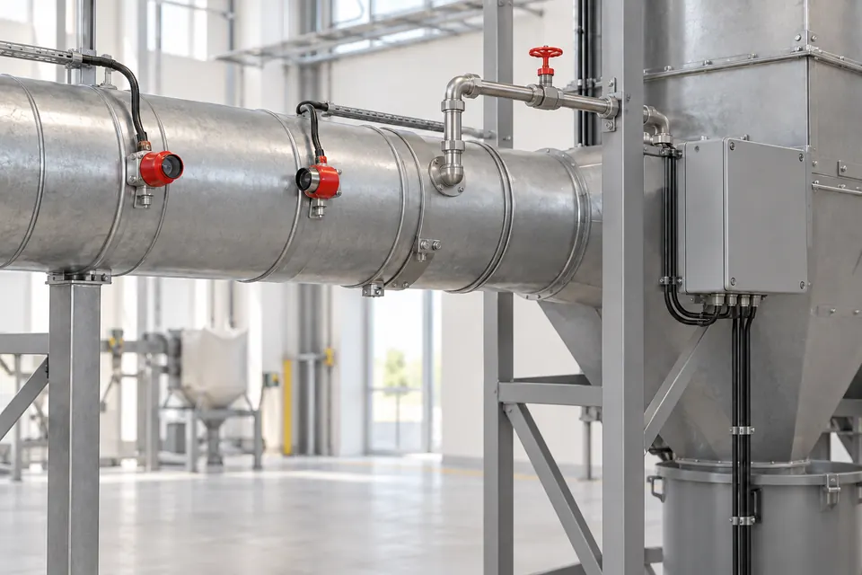
A suitable optical sensor detects radiation from sparks or hot particles within its field of view. Ambient light, process temperature and dust deposits influence detector selection. Opposing detector positions or a manufacturer lens-cleaning arrangement may be needed.
Signal processing and event recording
The controller links detection to the appropriate protection zone and manages alarms, event counts and process commands. Wiring faults, power loss and water-supply faults are included according to the monitoring functions of the selected system.
Fast valve and water distribution
When the valve opens, nozzles distribute water across the required duct section. Nozzle quantity, flow, spray geometry and residual supply pressure are selected together. Response time, pressure and spray duration are specific to the system configuration.
Post-event monitoring and safe shutdown
Monitoring continues after intervention. Persistent sparks, insufficient water or unsuccessful intervention may initiate alarms, material diversion or machine shutdown. Restart follows investigation of the cause and confirmation that the protection arrangement is ready.
02
Layout based on process conditions
Transport speed, duct size and combustible material differ between lines. Layout calculations and water, electrical and process interfaces are verified as part of the same design.
Timing and detection
- Detector-to-nozzle distance
- The required separation uses the highest transport velocity and the combined time for detection, control, valve opening and effective water distribution. Valve response time alone cannot establish the required protection distance.
- Hot and illuminated processes
- Detector type is selected for hot material, external light and contamination. A manufacturer cooling, purge-air or alternative sensing solution is used where needed; one temperature limit is not assigned to every line.
Supply and process compatibility
- Reliable water supply
- Required flow and dynamic pressure are checked for the simultaneous intervention scenario. Frost protection, filtration, valve access and any booster assembly form part of the design. A static gauge reading alone is insufficient.
- Material and diversion
- Quality, hygiene and process effects are assessed for water-sensitive materials. Any diversion arrangement needs a defined safe receiving area and verified actuator timing. Diversion does not provide explosion isolation unless separately validated for that function.
Verification and maintenance
- Fire and explosion protection
- Spark extinguishing is a layer of ignition prevention. Explosion venting, suppression and isolation require separate assessment. Combustible-dust projects consider the applicable design basis, including NFPA 660 where adopted, and any VdS certification scope for selected equipment.
- Functional and site checks
- Detector windows, water distribution, valves, alarms and shutdown interfaces are checked under the manufacturer maintenance programme. Records reveal event patterns and maintenance needs. Test intervals follow the equipment instructions and process risk assessment.
03
Protection for the transported material
Selection depends on ignition behaviour, transport method and the downstream equipment being protected, alongside the industry context.
Wood, MDF and chip handling
- Process hazard
- Cutting, sanding and drying can transport hot particles towards filters or silos.
- Protection approach
- Detection and extinguishing zones are positioned along the transport line, with separate assessment of filter, silo and dust-explosion protection.
Textile and fibre processing
- Process hazard
- Fibre transport, mechanical friction and dust deposits create different sensing conditions.
- Protection approach
- Lens cleanliness, field of view, product effects of water and the safe shutdown sequence are planned together.
Grain, feed, recycling and pellets
- Process hazard
- Foreign metal, crushers and dryers introduce ignition risks that vary with material and process.
- Protection approach
- Detection is selected for site conditions, considering hygiene, water compatibility, material deposits and other explosion-protection layers.
04
Different roles of the protection layers
Scroll the table horizontally to view every column.
| Layer | Primary function | Role in the design |
|---|---|---|
| Spark extinguishing | Early intervention on transported ignition sources. | Detection, transport velocity, water distribution and timing. |
| Shutdown / diversion | Stop hazardous process flow or divert it to a safe location. | Commands linked to event and fault scenarios. |
| Explosion isolation | Limit explosion propagation to connected equipment. | Separately validated equipment and explosion assessment. |
| Venting / suppression | Manage the pressure consequences of an explosion. | Enclosure, dust properties and site layout. |
VdS certification is assessed within the scope of the selected system and component. NFPA 660:2025 consolidates earlier combustible-dust standards, including NFPA 664; the project standard and local requirements are established separately.
Share the material, duct size, transport velocity and operating temperature so we can assess detection, intervention and safe shutdown together.