
Design and installation guide
Glass-door fire hose cabinet: visible equipment and practical access
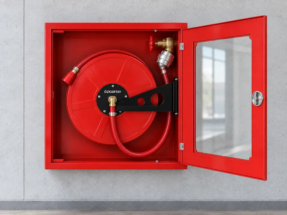
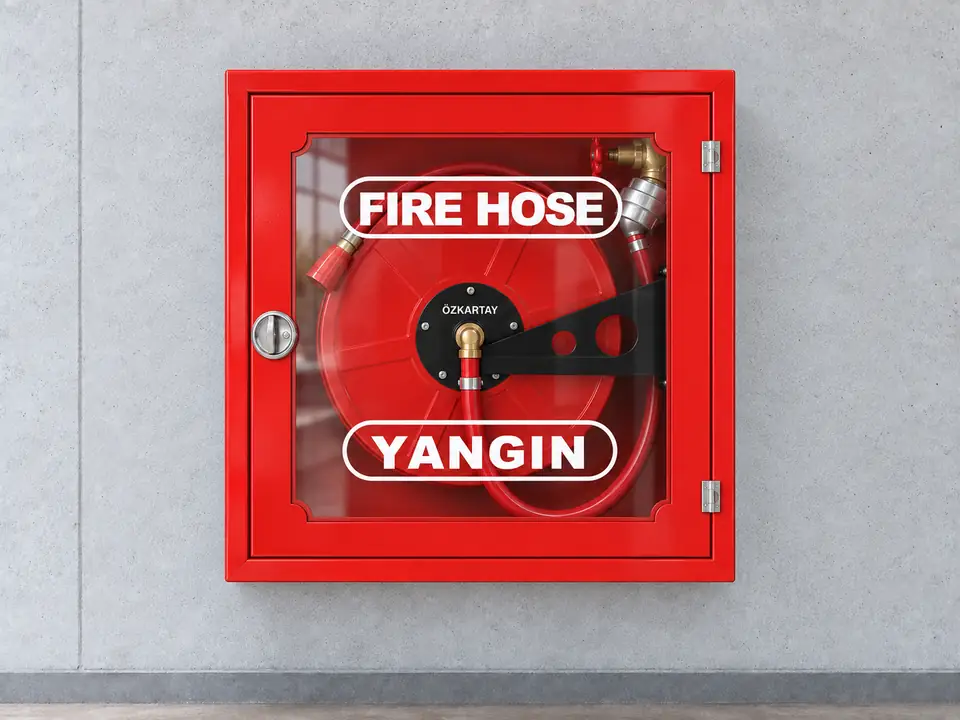
The glass door allows the hose reel and branchpipe to be seen from outside. Placement considers door opening, unobstructed hose deployment and the fire-water connection alongside visibility.
01
Product selection and installation planning
Selection brings the product connection and layout requirements together with the needs of the site.
Hose route
Select 20, 25 or 30 m hose against corridor turns and the actual deployment route.
Mounting and dimensions
Allow mounting space for the selected enclosure dimensions: 20 m hose model: 640 × 600 × 250 mm; 25 m hose model: 820 × 680 × 250 mm; 30 m hose model: 820 × 680 × 250 mm.
Water supply
Match the 2" (50 mm) fire valve and 2"–1" aluminium hose-tail coupling to the installation. Check branchpipe flow and pressure through the system design.
Visual checks and maintenance
Check the glass, lock, hinge, hose and brass rotating hub together, and keep the front of the cabinet clear.
02
Application planning for different spaces
These examples describe conditions to assess during the site survey. The fire protection design determines the final layout and equipment selection.
Offices and shared spaces
- Site requirement
- Easy equipment identification and access from the corridor.
- Planning approach
- Plan the door opening together with the circulation width.
Production and warehouse entrances
- Site requirement
- Material movement and changing storage layouts.
- Planning approach
- Locate the cabinet away from impact risks and stacks that could obstruct the hose route.
03
Selection and installation checklist
Scroll the table horizontally to view every column.
| Selection item | Product / option | Site check |
|---|---|---|
| Door | Tempered-glass or plexiglass door | Glass condition and opening space |
| Hose | 20 / 25 / 30 m | Actual route around walls and doors |
| Valve | TSE 12259-certified 2" (50 mm) fire valve | Pipe connection and hydraulic requirement |
| Enclosure | 20 m hose model: 640 × 600 × 250 mm; 25 m hose model: 820 × 680 × 250 mm; 30 m hose model: 820 × 680 × 250 mm | Wall opening and reel movement space |
Selection combines architectural appearance, access and water supply. Confirm the model, hose and valve options before quotation.