
Design and installation guide
Steel-door fire hose cabinet: organised installation and site fit
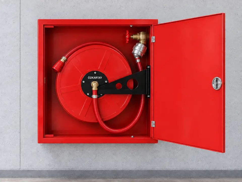
The steel-door model keeps the hose reel and branchpipe organised within a closed enclosure. The body is made from 1.2 mm galvanized sheet steel with red, white or black electrostatic powder coating. Wall and connection conditions determine the mounting arrangement.
01
Product selection and installation planning
Selection brings the product connection and layout requirements together with the needs of the site.
Wall and door clearance
Check circulation space for surface mounting, and the wall recess and supporting fixings for recessed mounting.
Hose and valve selection
Select the 20, 25 or 30 m hose and 2" (50 mm) fire valve according to the deployment route and water line.
Reel and connection
Leave movement space for the galvanized reel and brass central waterway, and assess hose bends and friction points.
Handover and maintenance
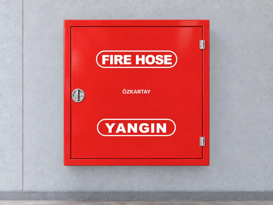
Include the door, lock, hose, valve and branchpipe in the maintenance plan. Identification keeps the equipment easy to locate with the door closed.
02
Application planning for different spaces
These examples describe conditions to assess during the site survey. The fire protection design determines the final layout and equipment selection.
Factory corridors
- Site requirement
- Frequent use and a clear equipment frontage.
- Planning approach
- Determine the door direction and location alongside site traffic.
Commercial building service areas
- Site requirement
- Wall recesses and limited circulation space.
- Planning approach
- Select a recessed configuration after checking the wall and pipe entry.
03
Selection and installation checklist
Scroll the table horizontally to view every column.
| Selection item | Product / option | Site check |
|---|---|---|
| Door and enclosure | Steel door; galvanized enclosure | Hinge, lock and surface condition |
| Mounting | Surface / recessed | Wall and fixing conditions |
| Hose | 20 / 25 / 30 m | Deployment route and branchpipe access |
| Enclosure size | 20 m hose model: 640 × 600 × 250 mm; 25 m hose model: 820 × 680 × 250 mm; 30 m hose model: 820 × 680 × 250 mm | Wall recess and connection fit |
The steel-door cabinet forms a response point with suitable placement and a maintained water supply. Confirm dimensions and connections against the selected model.