
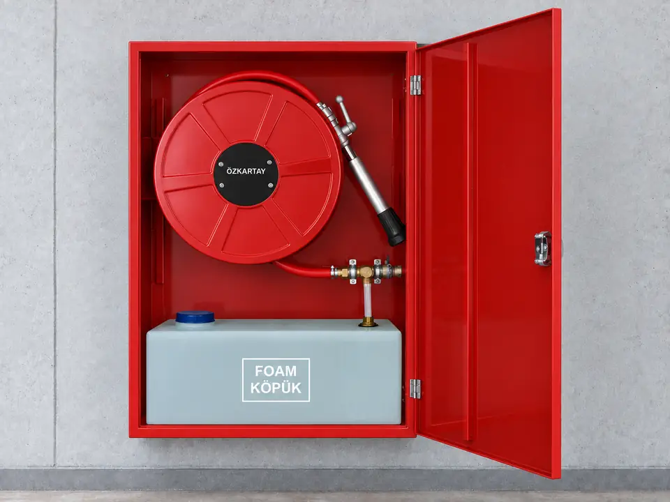

Design and installation guide
Foam-system fire hose cabinet: tank, proportioning and branchpipe compatibility
The foam cabinet combines the hose reel, concentrate tank and proportioning equipment in one enclosure. Cabinet dimensions: 20, 25 and 30 m hose models: 1000 × 700 × 260 mm; tank dimensions: 250 × 220 × 600 mm. Select the foam and tank from the liquid hazard, protected area and response plan together with the water supply.
01
Product selection and installation planning
Selection brings the product connection and layout requirements together with the needs of the site.
Fuel and concentrate
Select AFFF, AFFF-AR, synthetic or fluorine-free (NFF / F3) concentrate against the protected fuel and product data sheet. Match the exact ratio within the 3–6% range for AFFF, AFFF-AR and synthetic options to the product and proportioner; NFF / F3 proportioning and hardware compatibility follow the selected concentrate data sheet.
Tank and operating duration
Assess the 30, 40 or 50 L tank options alongside flow, proportioning ratio and required application duration.
Hose and pressure
The minimum water-line pressure is 4 bar. Assess the 20, 25 or 30 m hose, 2" (50 mm) fire valve and water supply together in the site design.
Foam proportioner and branchpipe
Check the match between the stainless-steel 100 L/min proportioner and stainless-steel 1" foam branchpipe. Follow the selected equipment instructions for cleaning and concentrate checks after use.
02
Application planning for different spaces
These examples describe conditions to assess during the site survey. The fire protection design determines the final layout and equipment selection.
Fuel and flammable-liquid areas
- Site requirement
- Foam compatibility with the fuel and access to the application area.
- Planning approach
- Select the concentrate, tank and branchpipe together and match the location to the response plan.
Production using solvents
- Site requirement
- Different chemical hazards, including water-miscible liquids.
- Planning approach
- Assess a concentrate verified for the fuel and a compatible proportioning arrangement.
03
Selection and installation checklist
Scroll the table horizontally to view every column.
| Selection item | Product / option | Site check |
|---|---|---|
| Tank | 30 / 40 / 50 L tank options | Flow, ratio and required duration |
| Cabinet dimensions | 20, 25 and 30 m hose models: 1000 × 700 × 260 mm | Mounting space and door clearance |
| Tank dimensions | 250 × 220 × 600 mm | Tank position inside the cabinet |
| Proportioning | AFFF / AFFF-AR / synthetic (3–6%); NFF / F3 (product data-sheet ratio) | Exact ratio from fuel, concentrate and proportioner compatibility |
| Water line | The minimum water-line pressure is 4 bar. | Hydraulic design for the selected setup |
| Discharge | Stainless-steel 100 L/min proportioner and stainless-steel 1" foam branchpipe | Hose, pressure and equipment compatibility |
Tank capacity alone does not determine discharge duration. Configure the cabinet by checking the fuel, proportioning ratio, actual flow and site access together.