
Design and installation guide
Puff and pipe leak testing: clear flow paths and verified piping integrity
Gaseous suppression depends on clean, intact installed piping as well as agent quantity and hydraulic calculations. Debris left during installation can affect nozzle outlets, while leaking joints can compromise the intended discharge.
A puff test uses controlled gas flow to assess the flow path and piping cleanliness. A pipe leak test examines leakage under defined test conditions. Room integrity testing assesses the enclosure ability to retain agent. These checks answer different questions and are reported separately.
01
From preparation to returning the system to service
Testing is performed by competent personnel using the selected suppression-system instructions, project design and applicable acceptance criteria.
Define the test boundary
Pipe routes, sizes, branches, nozzles and joints are checked against the installation drawings. Agent containers, release circuits and equipment outside the test boundary are isolated under the agreed procedure. Work timing and any temporary protection are coordinated with the operator.
Puff / controlled flow check
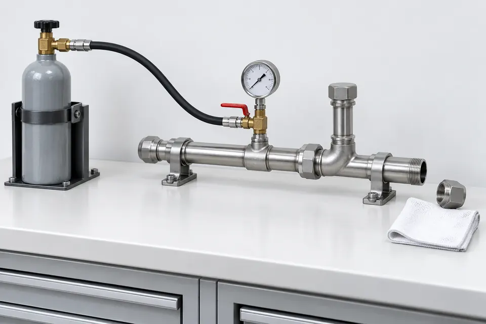
Manufacturer-approved dry air or nitrogen is passed through the defined piping in a controlled manner. Each outlet is checked for continuity and clearance of debris. Secure temporary connections, protected outlet areas and safe gas venting form part of the preparation.
Measure pipe leakage
Calibrated instruments record pressure and duration for leak testing. Stabilisation, ambient temperature and test volume are considered. Pressure and permitted change are checked against the system-specific acceptance criteria, rather than one percentage or duration for every gaseous system.
Final checks and records
Removed nozzles and temporary closures are restored under the procedure. Nozzle identification, orifice, direction and position are rechecked. Isolations are removed and control interfaces verified; test results, defects, repairs and retesting are included in the handover records.
02
Technical basis of the test plan
Method, measurement and acceptance criteria must refer to the same test boundary. Pipe cleaning, leakage assessment and strength testing are separate functions.
System and method
- Agent and piping
- Inert-gas and halocarbon systems may use different storage pressures, valve arrangements and piping designs. Storage pressure is not automatically the test pressure. Site testing follows the approved procedure for the installed system.
- Strength and leakage checks
- Strength testing assesses structural integrity under pressure; leak testing checks leakage behaviour. A puff test cannot replace either. Required tests, boundaries and acceptance criteria are identified separately in the plan.
Measurement and site safety
- Interpreting the measurement
- Instrument range, calibration, initial conditions and temperature changes are recorded. A pressure decrease cannot establish acceptance or rejection without its defined conditions. Results are assessed against the selected method.
- Controlled use of test gas
- Pressurised gas, temporary connections and vent points form part of the work plan. Ventilation and oxygen depletion are assessed where nitrogen is used in enclosed spaces. Personnel and sensitive equipment are protected during testing.
Handover and continued service
- Traceable test report
- The report identifies the system, boundary, method, instruments, conditions, readings and acceptance basis. Defects and required retesting remain visible. A successful measurement alone does not constitute insurance or regulatory acceptance of the whole system.
- Assessment after modifications
- Piping alterations, nozzle changes or repairs trigger assessment of the checks needed for the affected section. Clear flow paths and leak tightness complement verification of hydraulic calculations and final discharge equipment.
03
Use during commissioning and modifications
The installed gaseous system and affected pipe section determine the test scope alongside the facility use.
Data centres and electrical rooms
- Site condition
- Piping and multiple nozzles may surround sensitive equipment.
- Verification approach
- Venting and cleanliness are planned; piping checks are recorded separately from enclosure integrity testing.
New system installations
- Site condition
- Commissioning records are assembled after fabrication and installation.
- Verification approach
- Installation drawings, flow continuity, test results and final nozzle checks form one handover package.
Modifications and maintenance
- Site condition
- Extensions, branch changes or leak repairs may affect the previously verified installation.
- Verification approach
- Affected sections and calculations are reviewed, with required retesting and return to service recorded.
04
Three tests, three different questions
Scroll the table horizontally to view every column.
| Check | What is assessed? | Result |
|---|---|---|
| Puff test | Piping cleanliness and outlet flow continuity. | Clear flow path and cleaning record. |
| Pipe leak test | Piping and joint leakage under defined conditions. | Readings and acceptance against the procedure. |
| Room integrity test | Enclosure air leakage and agent retention behaviour. | Leakage area measurement and retention prediction. |
This guide explains the purpose of the tests. Applied pressures, durations and acceptance values are established in the test plan using the selected system instructions and project basis.
Share the system type, installation drawings and commissioning or modification scope so we can plan the piping checks and handover records together.