
Design and installation guide
Indoor fire hose cabinet systems: water supply, piping, layout and maintenance
A fire hose cabinet installation provides a permanent water supply for intervention in suitable early-stage fires inside a building. The water source, pump, risers, branch lines, valve, hose, reel and nozzle are designed together. Selecting a cabinet product is distinct from calculating the system supplying the building.
Design follows the Turkish Regulation on Fire Protection of Buildings. Semi-rigid hose reels are assessed under TS EN 671-1, lay-flat arrangements under TS EN 671-2, and maintenance under TS EN 671-3. Use is organised in accordance with the emergency plan and users’ training.
01
From the water source to the nozzle
System calculations aim to provide the required flow and pressure at the hydraulically most demanding cabinet.
Water reserve and pump set
Tank volume and operating duration are determined from the building hazard classification and simultaneous fire-water demand. Supply adequacy is verified and a suitable fire pump set selected where required. One fixed reserve duration is not applied to every building.
Flow and pressure calculations
For semi-rigid hose cabinets without a fire-service water outlet within the scope of Article 94, the design values are 100 L/min and 400 kPa, or 4 bar. Lay-flat hose cabinets are specified at 400 L/min and at least 400 kPa. A suitable pressure-reducing device is used when pressure at the nozzle inlet exceeds 900 kPa.
Wet and dry riser arrangements
A wet riser remains water-filled. A dry riser or another arrangement selected for frost conditions is designed with a defined method and timing of water delivery. A fire-service-fed dry riser does not operate in the same way as an always-pressurised hose-reel cabinet.
Piping and connections
Steel piping and grooved, threaded or suitable welded connections are selected for working pressure, corrosion exposure, building conditions and the adopted system standard. Riser diameter is calculated from simultaneous flow and line losses rather than assigned from floor count alone.
02
Equipment, layout and maintenance
Product equipment is considered together with the response method and actual access routes through the building.
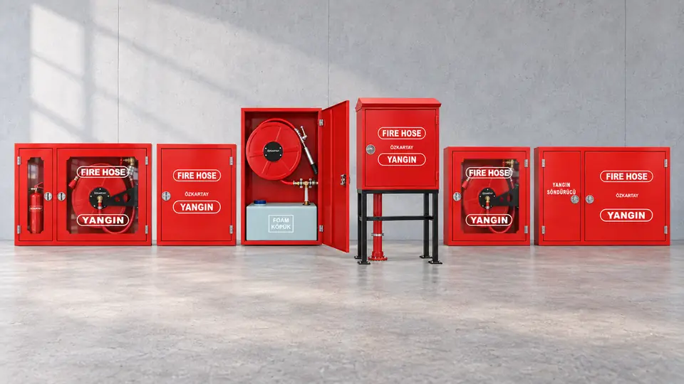
Cabinet and hose equipment
- Enclosure, door and valve
- A recessed or surface-mounted enclosure is selected for impact and corrosion exposure. The door opens without obstructing equipment removal. The supply valve and any pressure reducer are coordinated with flow calculations and maintenance access.
- Semi-rigid hose and rotating reel
- A TS EN 671-1 reel arrangement allows use with the required length of hose deployed. The relevant Turkish Article 94 application specifies 25 mm hose to TS EN 694, no longer than 30 m. The hub, hose connection and reel are checked together.
- Lay-flat hose arrangement
- A TS EN 671-2 arrangement is assessed for trained personnel able to deploy and connect hoses. The relevant regulation specifies lay-flat hose with a nominal diameter no greater than 50 mm and length no greater than 20 m; it must be deployed suitably before use.
- Controllable nozzle
- Shut-off and the selected spray or jet functions are matched to the hose and supply values. Actual reach is assessed using the hose route, obstacles and documented nozzle performance rather than one fixed jet range for every model.
Indoor layout
- Floors and coverage
- The regulation generally places cabinets on each floor and in sections separated by fire walls at intervals no greater than 30 m. The relevant arrangement with sprinkler protection and floor-level fire-service water outlets permits assessment of spacing up to 45 m. Actual hose routes are checked on the plan.
- Visibility and access
- Visible positions near corridor exits, stair landings and entrances are assessed. Cabinets remain unobstructed, are not hidden by decorative coverings and do not restrict evacuation. Mounting height follows product instructions, accessibility and the architectural layout.
- Fire hazards suitable for water
- Cabinet selection takes combustible materials into account. Water application is not assumed suitable for energised electrical equipment or materials that react dangerously with water. Foam-assisted options require separate confirmation of agent, proportioner and fuel scope.
Periodic inspection and testing
- Visual inspections
- Access, valve position, hose, nozzle, reel, connections and corrosion are checked under the operator’s programme. Defects are recorded, and inspection intervals follow TS EN 671-3 and the selected product instructions.
- Operation and flow verification
- Hose deployment, reel rotation, nozzle functions, leaks and supply performance are verified by a suitable operating test. Calibrated measurements are compared with the design and acceptance records.
- Pressure testing and maintenance records
- Periodic hose pressure testing and piping acceptance testing are different procedures. Test pressure and interval follow the applicable standard and product instructions. Results and replaced parts are retained in maintenance records.
03
Hose cabinet solutions by building type
Cabinet type is selected for personnel training, combustible materials, architecture and system water demand.
Residential, office, hotel and retail buildings
- Building requirement
- Visible initial-response equipment and varied user profiles.
- Selection approach
- Semi-rigid hose arrangements, a suitable enclosure and clear access are selected under the applicable regulation, with use defined in the emergency plan.
Production facilities
- Building requirement
- Impact, dust and varied process fire hazards.
- Selection approach
- Enclosure and finish are selected for the environment. Lay-flat hose requirements for trained personnel and the higher system flow are calculated separately.
Logistics warehouses
- Building requirement
- Long aisle routes, material movement and access obstacles.
- Selection approach
- Cabinet positions are assessed along actual rack and aisle routes. Where needed and suitable for a liquid hazard, foam assistance is planned using documented equipment.
04
Compare semi-rigid and lay-flat hose arrangements
Scroll the table horizontally to view every column.
| Item | Semi-rigid hose / TS EN 671-1 | Lay-flat hose / TS EN 671-2 |
|---|---|---|
| Hose arrangement | On a reel; the required length can be deployed. | Connected and suitably laid out. |
| Relevant Article 94 dimensions in Türkiye | 25 mm diameter; no longer than 30 m. | Nominal diameter no greater than 50 mm and length no greater than 20 m. |
| Applicable design flow / pressure | 100 L/min / 400 kPa in the applicable arrangement without a fire-service water outlet. | 400 L/min / at least 400 kPa in the applicable arrangement. |
| Use and training | Under the emergency plan and user training. | By trained personnel able to deploy and connect hoses. |
The values describe the relevant Turkish regulatory application; they are not a new performance declaration for an individual cabinet model or rotating hub.
Share the building plan, water supply and operating conditions with Özkartay so cabinet placement, piping calculations and product options can be assessed together.