
Design and installation guide
Outdoor fire hydrant systems: water networks, site layout, supply and maintenance
An outdoor hydrant system supplies water for external firefighting at production facilities, logistics centres, commercial buildings and residential developments. Hydrants used by the fire service, the water reserve, pump set and outdoor piping network form one system.
Layout and hydraulic calculations follow the Turkish Regulation on Fire Protection of Buildings and the design basis adopted for the project. Above-ground hydrant product requirements are assessed against TS EN 14384; NFPA 24 for piping, NFPA 20 for pumps and NFPA 25 for operation are considered where applicable to the project.
01
Hydrant network and water supply
The reserve, simultaneous demand and pressure losses are calculated together to deliver the required water to the most demanding response location.
Fire-water reserve
Tank capacity is established from the hazard classification, required duration and other fire systems sharing the supply. Water-source reliability and the pump set are planned for the demand of the complete fire scenario.
Design flow and pressure
In Türkiye, Article 95 specifies a minimum system design flow of 1,900 L/min and a hydrant outlet pressure of 700 kPa, or 7 bar. This system flow does not mean that every individual hydrant delivers the same flow; simultaneous use, hazard classification and hydraulic losses are assessed in the calculation.
Ring network and section isolation
A ring network with suitable valve arrangements can provide alternative supply paths to hydrants. An affected section can be isolated during maintenance or a fault to support operation elsewhere. Its effect on pressure loss is calculated hydraulically rather than assumed to be a fixed 50% reduction.
Pipe material and sizing
Pressure-rated materials such as suitable HDPE or ductile iron may be considered for buried lines. The Turkish regulation specifies a minimum pipe diameter of 100 mm where no ring arrangement is provided. Larger sizes are selected from simultaneous flow, pipe length, pressure and ground conditions.
02
Hydrant types, site layout and maintenance
Climate, fire-service connections and access determine hydrant type, while hazard classification and the building perimeter determine placement.
Hydrants and response equipment
- Above-ground dry-barrel hydrant
- The main valve and drainage arrangement are designed below ground for local frost conditions. Draining the barrel after closure reduces freezing risk; blocked drainage or high groundwater can affect this function and require separate site and maintenance checks.
- Wet-barrel and underground hydrants
- A wet-barrel hydrant remains water-filled and is assessed for conditions without freezing risk. An underground type is protected in a covered box and used with a suitable standpipe. Article 95 in Türkiye specifies above-ground hydrants; suitability of underground types for other applications is assessed separately with the relevant authority and specification.
- Outlets and Storz couplings
- Outlet quantity, nominal size and coupling types such as Storz are selected from the hydrant documentation and local fire-service equipment. Hose and fire-appliance connections serve different functions, so their arrangement is verified at handover.
- Outdoor equipment cabinet
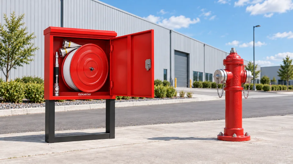
- Hoses, a controllable nozzle and a hydrant key are protected from outdoor exposure in an accessible cabinet. Cabinet material, equipment quantity, hose length and its location relative to the hydrant are selected for the response plan.
Site layout
- Spacing by hazard classification
- Article 95 gives hydrant spacing as 50 m for very high-risk areas, 100 m for high-risk areas, 125 m for medium-risk areas and 150 m for low-risk areas. The applicable classification is determined using building and combustible-material information.
- Building perimeter and safe approach
- Under normal conditions, the average 5–15 m distance between the building and hydrant described in the regulation is considered. Fire-appliance access, connection space, radiant heat and potential structural damage are included in the same layout assessment.
- Impact protection and access
- Suitable barriers are planned where forklifts and vehicles operate without obstructing caps or hose connections. Operation keeps the hydrant clear of pallets, parked vehicles and vegetation.
Testing, maintenance and records
- Visual and functional inspection
- Caps, couplings, valves, coatings, corrosion and physical damage are checked under the maintenance plan. Operation, flushing and leak tests are performed by qualified personnel to the selected standard and manufacturer programme.
- Pressure and flow measurement
- Static pressure, flowing pressure and flow are measured using suitable calibrated instruments. The test point, outlets operating simultaneously and test conditions are recorded and compared with the design values.
- Winter preparation and drainage
- Sites exposed to frost check dry-barrel drainage and residual water. Sections taken out of service for maintenance are recorded, and temporary arrangements needed to maintain response capability are coordinated with the operator.
03
Hydrant solutions for different facilities
Site size, vehicle movements and fire load can require different infrastructure and layouts around the same hydrant product.
Production facilities
- Site requirement
- A large site and fire loads from different processes.
- Design approach
- Supply, section isolation and hydrant access are designed together. Additional foam equipment is assessed in flammable-liquid areas after fuel and agent compatibility are confirmed.
Logistics warehouses
- Site requirement
- Heavy truck and forklift movements with extensive outdoor storage.
- Design approach
- Protected hydrants and connection areas are planned with a water network covering the site, and fire-appliance approach routes remain clear.
Shopping centres, campuses and residential sites
- Site requirement
- Shared pedestrian spaces, landscaping and vehicle routes.
- Design approach
- Above-ground hydrants meeting the applicable regulation are coordinated with landscaping while retaining visibility and fire-service access. Suitable impact protection is planned along vehicle routes.
04
Compare hydrant types
Scroll the table horizontally to view every column.
| Item | Above-ground dry barrel | Above-ground wet barrel | Underground |
|---|---|---|---|
| Water and frost conditions | The barrel drains after closure when drainage is suitable. | The barrel remains water-filled; frost exposure is assessed. | Valve and drainage conditions depend on the selected model. |
| Response connection | Hoses connect to visible outlets. | Hoses connect to visible outlets. | The cover is opened and a suitable standpipe and key are used. |
| Vehicle and site conditions | Suitable impact protection and clear access. | Suitable impact protection and clear access. | Box load rating, marking and access checks. |
| Maintenance focus | Drainage, valve, caps and connections. | Valve, leaks and connections. | Box cleanliness, cover and connection equipment. |
This type comparison does not alter the above-ground hydrant requirement under Article 95 in Türkiye. Use of an underground type requires separate assessment against the authority and specification for that application.
Review the site layout, water source and response requirements with Özkartay so the hydrant network and product options can be planned within one engineering design.