
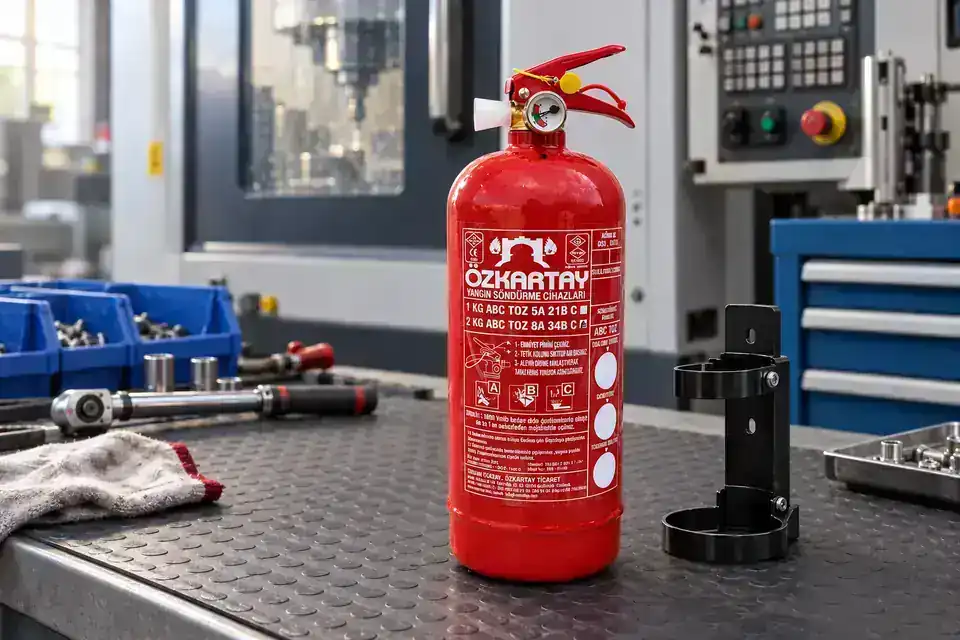
 1 kg ABC 40% or 90% extinguisher
Portable fire extinguishers
Portable first-response equipment; type and capacity are set through risk assessment.
Explore the fire extinguisher components
Explore ceiling components and how they work
Explore the design and installation guide
Catalogue options
Products
1 kg ABC 40% or 90% extinguisher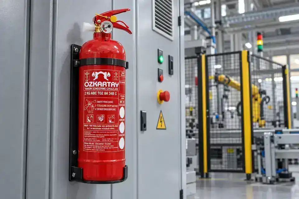 2 kg ABC 40% or 90% extinguisher
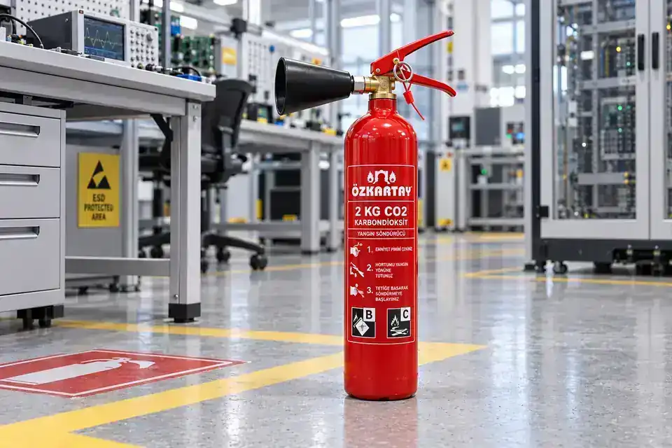 2 kg carbon dioxide (CO₂) extinguisher
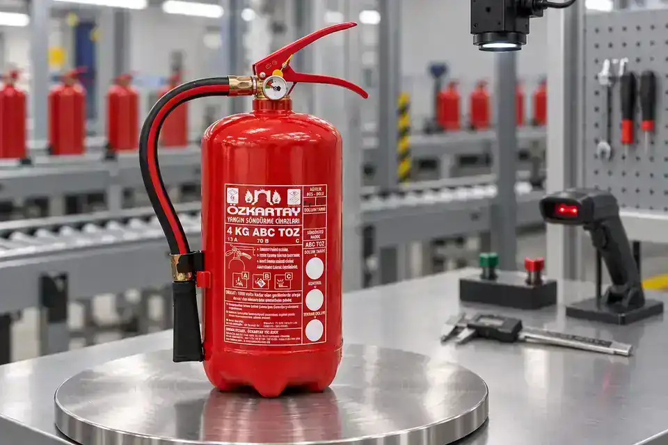 4 kg ABC 40% or 90% extinguisher
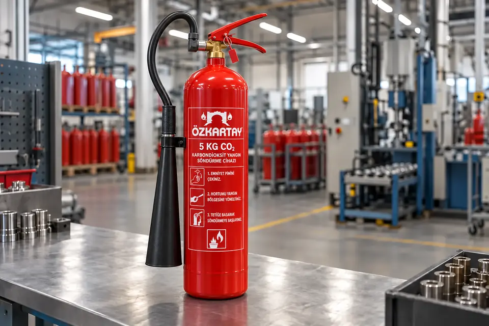 5 kg carbon dioxide (CO₂) extinguisher
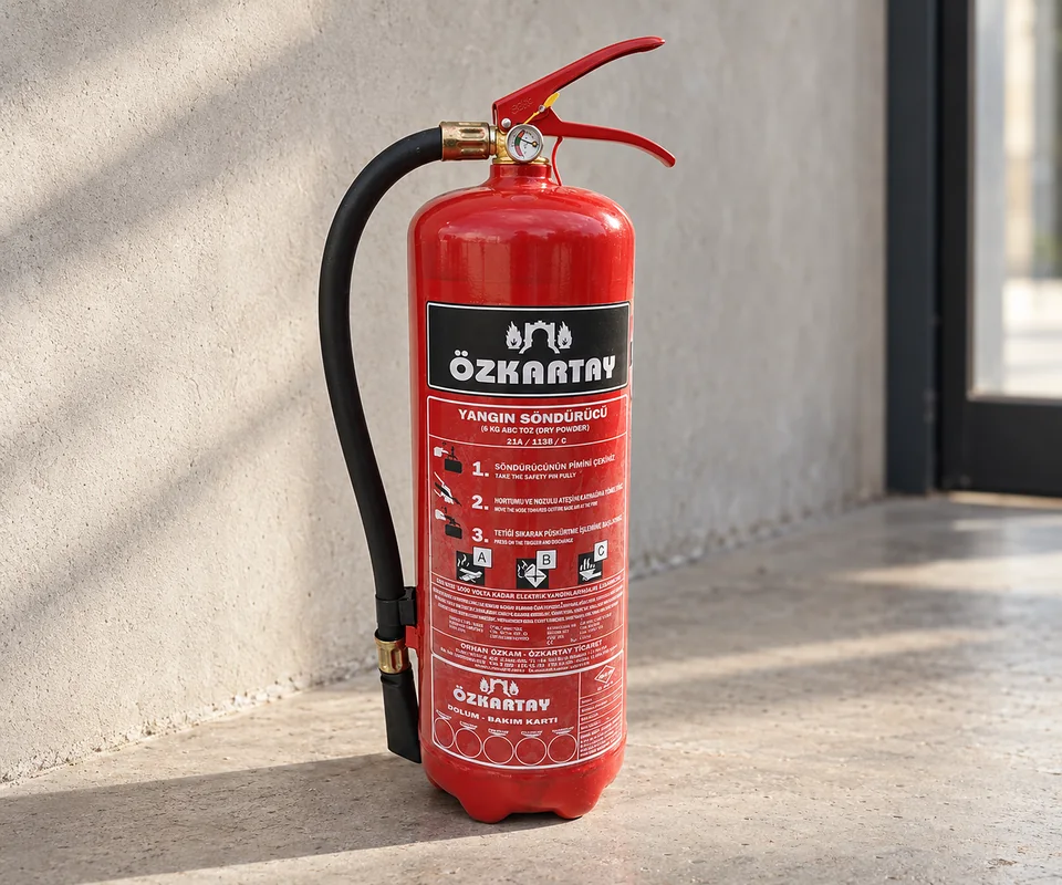 6 kg ABC 40% or 90% extinguisher
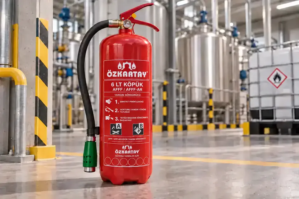 6 LT AFFF, AFFF-AR, synthetic or fluorine-free (NFF / F3) foam extinguisher
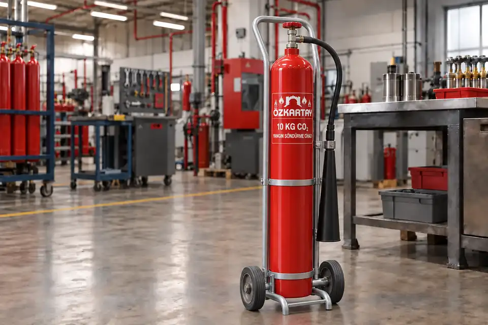 10 kg carbon dioxide (CO₂) extinguisher
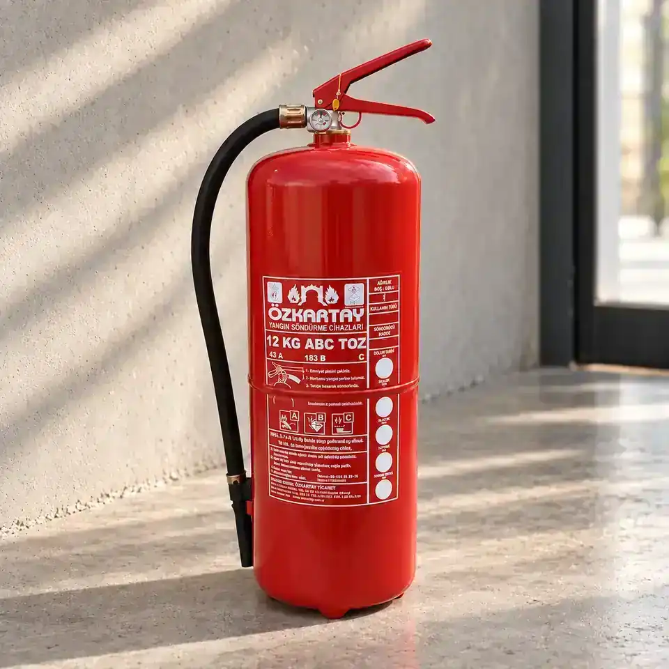 12 kg ABC 40% or 90% extinguisher
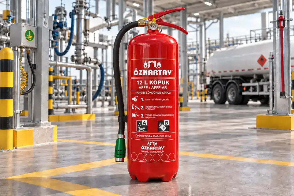 12 LT AFFF, AFFF-AR, synthetic or fluorine-free (NFF / F3) foam extinguisher
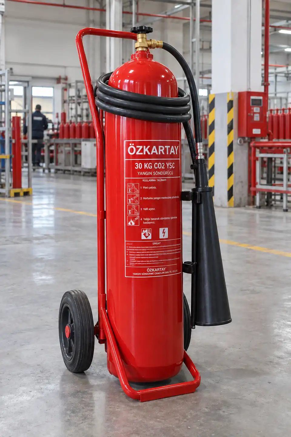 30 kg carbon dioxide (CO₂) extinguisher
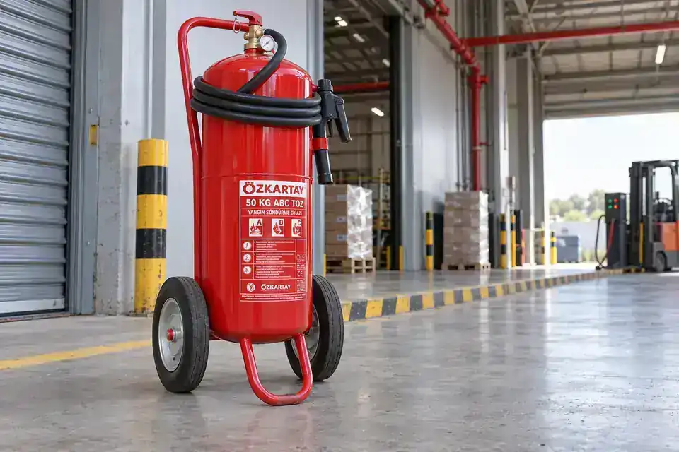 50 kg ABC 40% or 90% extinguisher
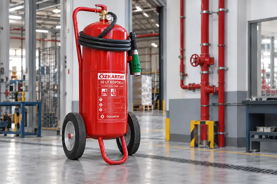 50 LT AFFF, AFFF-AR, synthetic or fluorine-free (NFF / F3) foam extinguisher
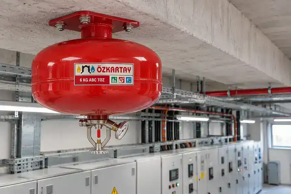 6 kg ABC 40% or 90% ceiling-type extinguisher
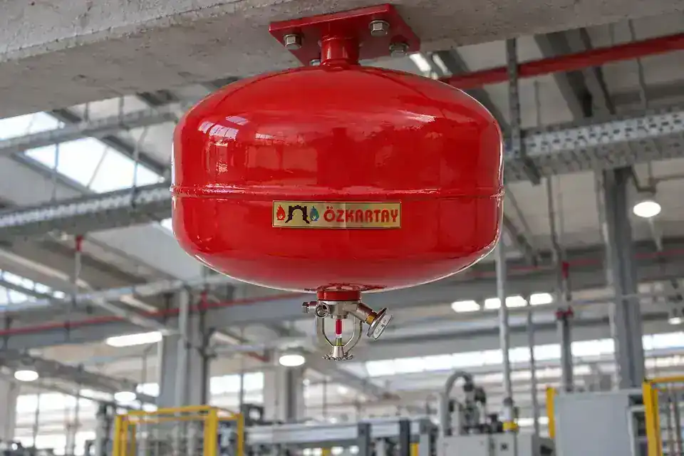 6 LT AFFF, AFFF-AR, synthetic or fluorine-free (NFF / F3) foam ceiling-type extinguisher
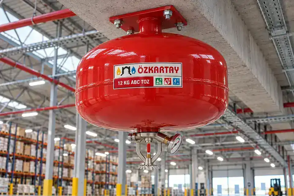 12 kg ABC 40% or 90% ceiling-type extinguisher
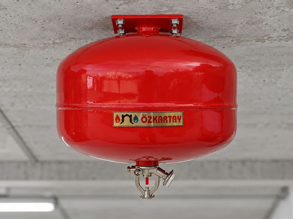 12 LT AFFF, AFFF-AR, synthetic or fluorine-free (NFF / F3) foam ceiling-type extinguisher
EXPLORE THE COMPONENTS
Every component has a purpose.
Explore the main components of a stored-pressure ABC powder extinguisher and the qualities to consider. The illustrations are representative; component geometry and materials vary by model.
A flow from the cylinder to the nozzle.
The dip tube carries the extinguishing agent from the cylinder to the valve. When the operating lever opens the valve, the agent is directed through the hose and nozzle. These components work together as an assembly.
This guide covers an ABC powder extinguisher with a pressure gauge. CO₂ extinguishers use a different valve and discharge arrangement; their charge is checked by weight.
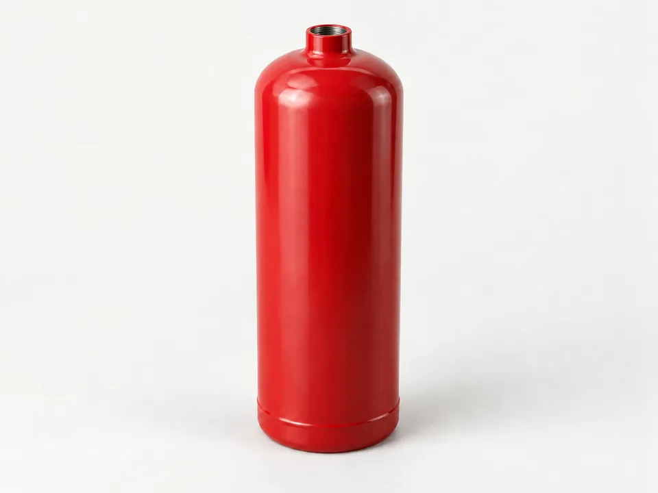
Pressure cylinder
The cylinder contains the extinguishing agent and propellant gas. The neck at the top provides the connection to the valve.
- What to look for in quality
- Cylinder strength, the neck connection, corrosion protection and the model’s pressure tests.
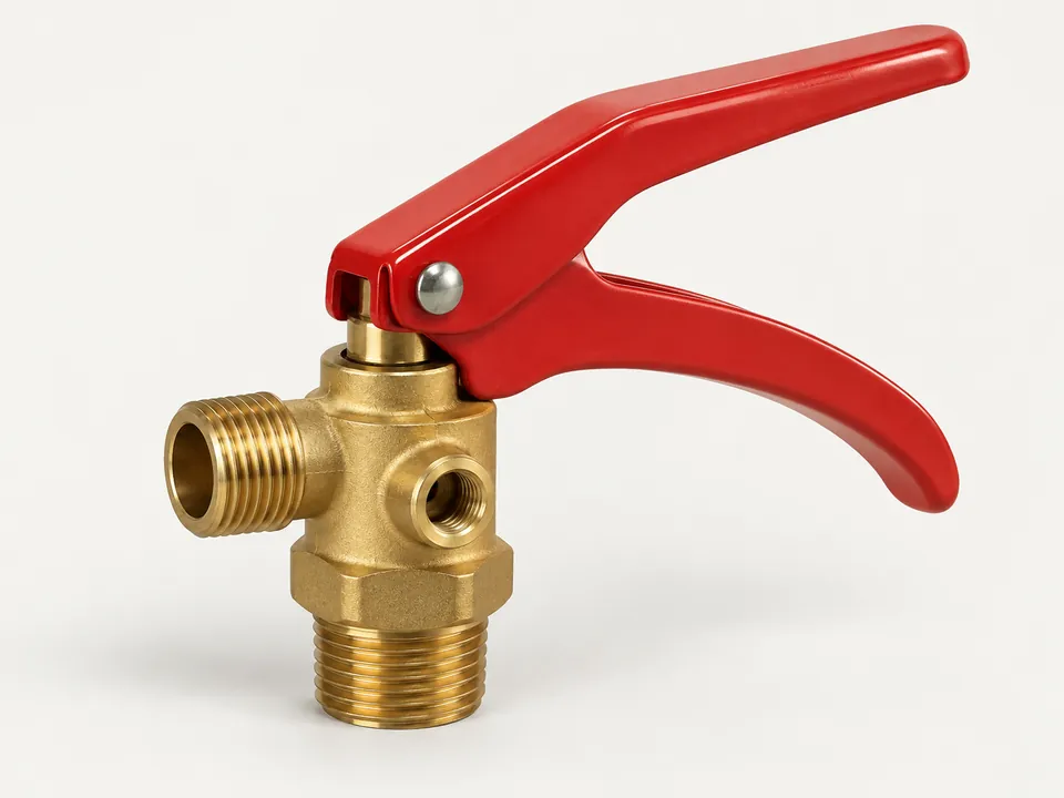
Valve and operating lever
The carrying handle supports the extinguisher while the upper operating lever opens the valve. The valve controls the release of the extinguishing agent.
- What to look for in quality
- Smooth lever and hinge movement, model-compatible seals and threads, and a leak-tight valve-to-cylinder connection.
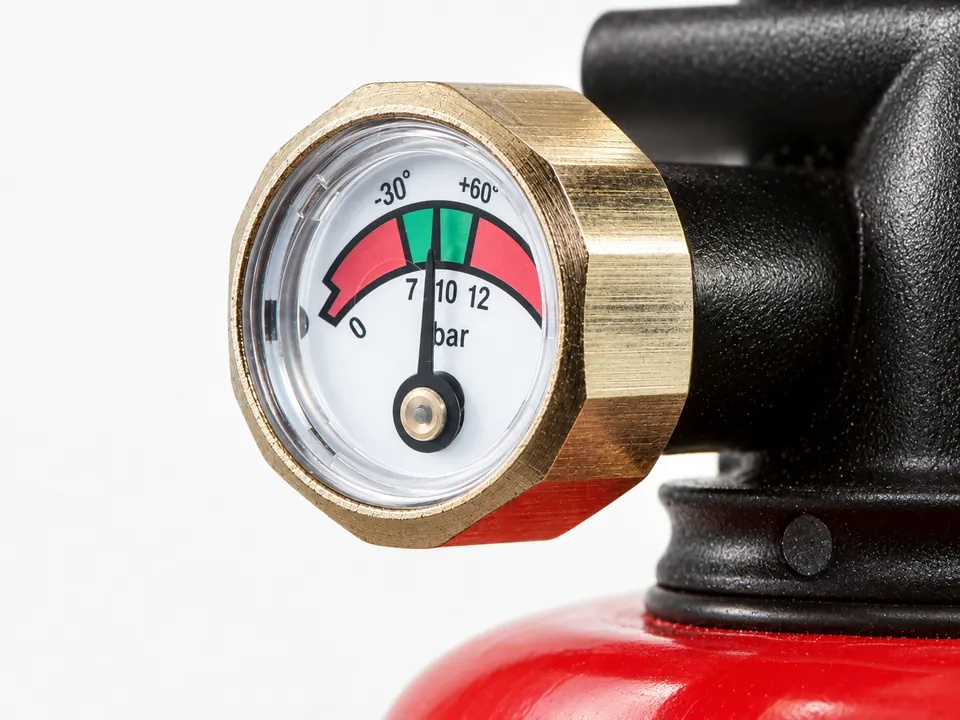
Pressure gauge
The gauge provides a visual indication of internal pressure. A needle in the operating range does not, on its own, show how much powder remains.
The dial follows the supplied visual reference. The selected extinguisher’s pressure rating is verified from its own label and data sheet.
- What to look for in quality
- A legible needle and operating range, the correct gauge for the model and a leak-tight connection.
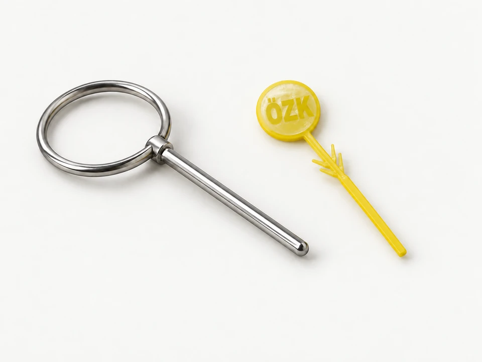
Safety pin and tamper seal
The safety pin prevents accidental lever operation. The tamper seal helps indicate whether the pin has previously been removed.
Yellow round-head tamper seal stamped ÖZK beside a metal safety pin.
- What to look for in quality
- A properly fitting, removable pin, an easy-to-grip ring and a visibly intact tamper seal.
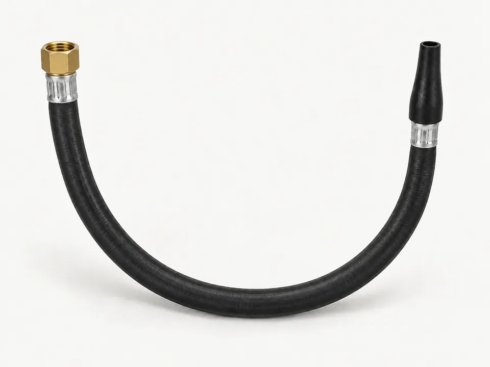
Hose and nozzle
The flexible hose carries the agent from the valve to the discharge outlet. The nozzle directs the discharge; its shape and connection depend on the extinguisher type.
- What to look for in quality
- An unobstructed, crack-free hose, secure connections and a hose-and-nozzle assembly compatible with the model.
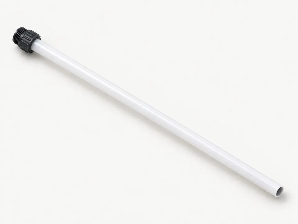
Dip tube / siphon tube
The dip tube extends inside the cylinder from the valve towards the bottom. It forms the internal passage that carries the agent to the valve.
- What to look for in quality
- The correct length and connection for the extinguisher, a clear passage and an undamaged tube, checked during qualified servicing.
INSIDE THE CEILING UNIT
Detects heat, discharges downwards.
A ceiling extinguisher carries its agent in its own vessel. Explore the body, ceiling mount and heat-sensitive discharge head separately. This mechanical guide is representative; powder and foam models can differ in agent and head arrangement.
Why a wide body and a head underneath?
A wide, shallow vessel provides a compact ceiling arrangement. Its rounded form relates to pressure-vessel construction. The lower head is exposed to rising heat and directs agent towards the protected area; the actual distribution is established through model-specific testing.
How does it work?
Heat reaches the head
The thermal element responds to a temperature rise around it; it does not operate as a smoke detector.
The sealed outlet is released
The special liquid inside the thermal glass bulb expands with heat. A red bulb has a nominal activation temperature of 68 °C; the broken bulb releases the outlet.
Agent is distributed
Vessel pressure drives agent through the discharge head. The outlet and deflector shape the direction of the flow.
ABC powder options
The vessel contains dry chemical powder. Powder composition, charge quantity and discharge arrangement are assessed with the selected product’s technical information.
Foam options
The vessel contains a foam extinguishing solution suitable for the model. Foam blanketing and water-based cooling depend on the agent; the head need not be identical to a powder model’s.
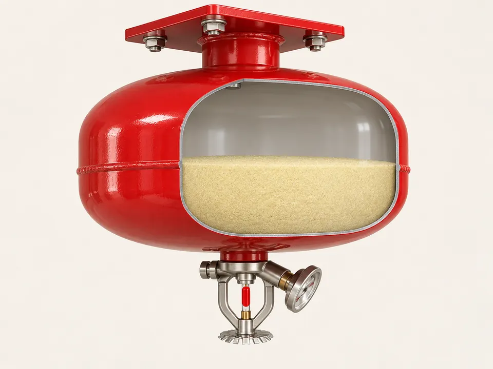
Schematic ABC powder example; internal geometry and fill level are not to scale.
Vessel and contents
In a stored-pressure example, the vessel contains agent and propellant gas. The cutaway schematically illustrates an ABC powder example.
- Why this shape or arrangement?
- The shallow, wide, rounded vessel suits a ceiling arrangement; its shape alone does not indicate capacity or pressure.
- What matters when selecting the component?
- Vessel integrity, coating, a model-compatible charge and documented vessel tests.
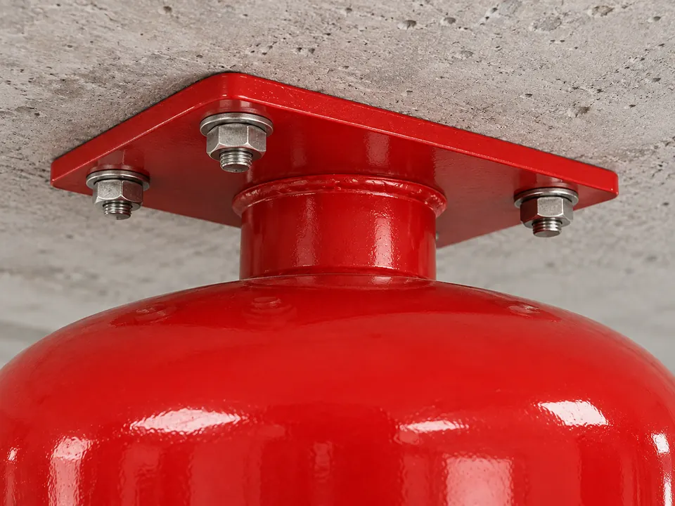
Representative component illustration
Ceiling plate and supporting connection
The upper plate transfers the unit’s weight to the mounting surface. The neck and connections support the vessel below the plate.
- Why this shape or arrangement?
- The plate’s fixing points spread the load into the mounting surface. Supporting the unit from above leaves its lower discharge head exposed.
- What matters when selecting the component?
- The supporting surface, appropriate fasteners and the mounting position specified for the product.
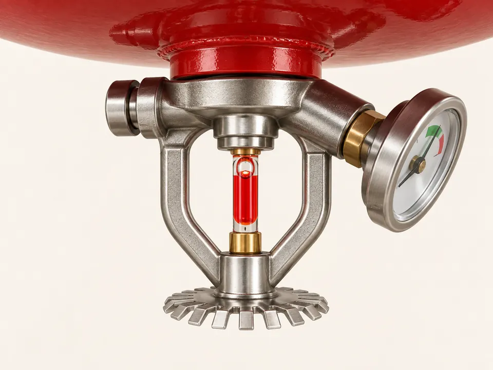
Representative component illustration
Heat-sensitive release element
This component is a thermal glass bulb. Its special heat-sensitive liquid expands to break the bulb and open the sealed outlet. A red liquid-filled bulb has a nominal activation temperature of 68 °C.
- Why this shape or arrangement?
- The slender, exposed bulb is subject to surrounding heat. The metal frame aligns the bulb with the outlet assembly.
- What matters when selecting the component?
- An undamaged bulb and a model-compatible thermal element. Activation temperature is verified from the head and product data sheet.
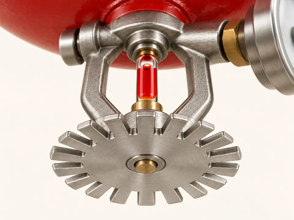
Representative component illustration
Outlet and distribution head
Agent leaving the open outlet is directed by the head geometry. In an example with a deflector plate, the plate helps spread the flow.
- Why this shape or arrangement?
- The plate’s edge shape affects flow direction. Protected area cannot be calculated from the plate’s appearance or the vessel diameter alone.
- What matters when selecting the component?
- An unobstructed outlet, undamaged head and a distribution arrangement verified for the selected agent.
Design and installation guide
Fire extinguishers: selecting the agent, capacity and position for the hazard
Fire extinguishers are selected for suitable fires at an early stage. Selection depends on the burning material, the extinguisher’s labelled rating, capacity, environment and user training.
Özkartay’s ABC dry powder, CO₂ and foam extinguishers serve different needs. Portable, wheeled and ceiling-mounted variants are assessed against their own operating conditions; capacity alone does not establish suitability.
01
Five checks for extinguisher selection
Consider response equipment together with the facility’s risk assessment and evacuation plan.
Fire class and electrical hazard
In EN classification, A refers to solids, B to flammable liquids and C to flammable gases. Assess suitability for energised electrical equipment separately; class letters can differ between standards systems.
Agent compatibility
Consider powder residue, foam compatibility with the fuel and exposure from CO₂ in enclosed spaces. Special risks such as cooking oils or metals require equipment rated for the relevant fire class.
Capacity and use arrangement
Assess portable weight and wheeled-unit access with the intended user. All foam devices in the catalog are specified in LT (litres); litres and kilograms are different capacity measures.
Position and visibility
Position units where they are accessible, visible and coordinated with escape arrangements. Check for access blocked by storage, locked rooms or equipment during site inspections.
Labels, maintenance and records
Match agent, capacity, conformity documentation and maintenance records to the selected model. Inspect the vessel, discharge hardware and any fitted seals or indicators. Özkartay CO₂ devices have no pressure gauge; charge is checked by weight. Ceiling devices also require checks on the thermal glass bulb and fixed mounting.
02
ABC, CO₂ and foam options
Verify agent selection against the approved uses on the extinguisher label.
ABC dry powder
- Application
- Catalog ABC models are offered for A, B and C risks. For electrical hazards, follow the label and technical documentation.
- Environmental effect
- Assess powder residue in relation to sensitive equipment, visibility and clean-up needs.
Carbon dioxide (CO₂)
- Application
- Consider as a residue-free option around electrical and electronic equipment; check the model label for its fire rating.
- Safe use
- Account for CO₂ exposure in enclosed spaces and cold discharge components. Use and maintenance follow the selected model’s instructions.
Foam extinguishers
- Application
- Assess AFFF, AFFF-AR, synthetic or fluorine-free (NFF / F3) options for the liquid involved; match agent, proportioning and device compatibility to the product documentation.
- Limitations
- Do not assume foam is suitable for every fuel or energised electrical equipment. Cooking-oil hazards require an approved solution for that risk rather than a general Class B foam unit.
03
Extinguisher planning by facility use
Agents are not automatic substitutes for one another; assess different spaces in the facility separately.
Workshops and production
- Risk
- Solid materials, flammable liquids and electrical equipment may coexist.
- Selection approach
- Select agents against the material inventory and labelled ratings; plan access and working space for wheeled units.
Offices, IT and electrical rooms
- Risk
- Electronic equipment and sensitivity to powder residue.
- Selection approach
- Assess electrical suitability and residue together; consider ventilation and personnel exposure when choosing CO₂.
Spaces using flammable liquids
- Risk
- Response needs vary with fuels and solvents.
- Selection approach
- Match foam type to the fuel. Include open or enclosed conditions, quantities and the response plan in capacity selection.
Ceiling-mounted applications
- Risk
- Mounting height and the local protected hazard.
- Selection approach
- Select ceiling-mounted units against their own documentation and activation conditions; plan building sprinkler protection and other protection layers separately.
04
Agent selection comparison
Scroll the table horizontally to view every column.
| Agent / arrangement | Need considered | Check required |
|---|---|---|
| ABC powder | A / B / C risks covered by the label | Residue and user conditions |
| CO₂ | Suitable electrical and liquid risks | Label, exposure and maintenance |
| Foam | Compatible flammable-liquid hazard | Fuel / concentrate compatibility |
| Ceiling mounted | Defined local application | Mounting and activation conditions |
Extinguisher use requires training and a safe escape route. If the fire grows or intervention is unsafe, prioritise the alarm, evacuation and professional assistance.
The right extinguisher is selected for the hazard, kept accessible and supported by maintenance records. Establish the space, agent and operating conditions before quotation.